APPROVED FOR EXTERNAL DISTRIBUTION
– PROPERTY OF AMPCONTROL PTY LTD
– NOT TO BE REPRODUCED IN PART
5.3.2 Remote Display Module (RDM-D)
The Remote Display Module is an intrinsically safe device (Ex ia), designed to be mounted into the cut
out of an IP54 enclosure and can therefore be mounted external to the switchgear it is controlling. To
provide maximum benefit to the operator, one RDM is normally used per relay. This allows information
from several relays to be simultaneously accessed and compared. However, if space restrictions
preclude this, a compromise is to use one (1) RDM-D to monitor and control more than one IPD Relay.
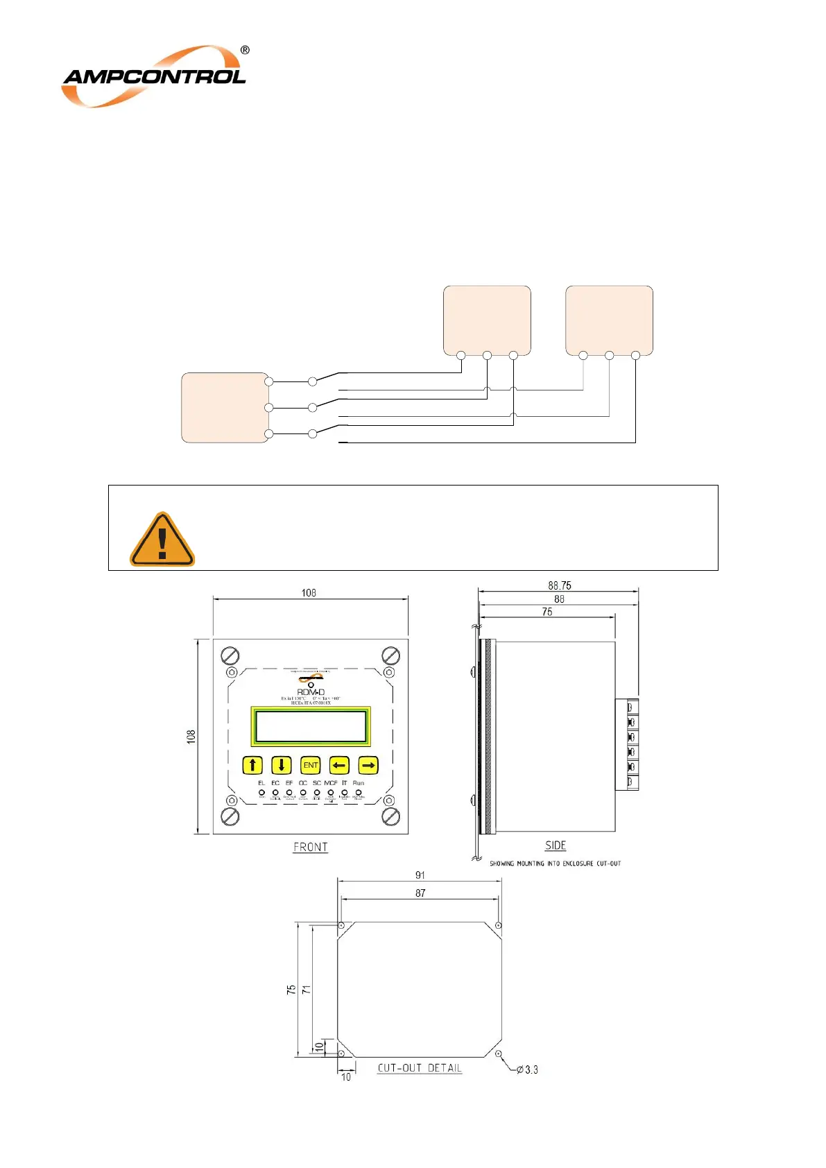
In these circumstances the following wiring arrangement is recommended:
Figure 5.3: Optional RDM Installation Arrangement
The 3 pole change over switch must have sufficient clearance and
creepage allowance between IPD Relay channels in accordance with
IEC installation requirements.