Ampcontrol Pty Ltd – ABN 28 000 915 542
IPD USER MANUAL
IPDB014 Version 14 – SEP/2020
Uncontrolled Copy - Refer to Ampcontrol Website for Latest Version
APPROVED FOR EXTERNAL DISTRIBUTION
– PROPERTY OF AMPCONTROL PTY LTD
– NOT TO BE REPRODUCED IN PART
For the IPD, transient overreach may cause spurious tripping on short circuit due to resulting
measurement inaccuracies. To compensate for this effect, a ‘START TRANSIENT’ mode has been
implemented, with the following selectable options on Level 9, Position 16 of the Remote Display
Module: OFF, 40ms, 60ms, 80ms, 100ms or 120ms.
When the START TRANSIENT mode is enabled, the IPD current setting is increased for the specified
period of time, after the main contactor has been closed. The increased current is achieved by the
following:
1. For current multiplier 1/8x to 2x, the current multiplier will be increased one step (e.g. 1/2x
increases to 1x for the selected time period)
2. For current multiplier 4x, the base current will be increased to the maximum setting of 116A.
Example 1: Start Transient Setting
IPD set to 88A, 1x current multiplier and 6x short circuit multiplier,
resulting in a short circuit set point of 528A.
With START TRANSIENT mode set to 90ms, the current multiplier goes
to 2x, and the short circuit trip level will increase to 1136A until 90ms
after the MCI input (from the auxiliary contact on the main contactor)
closes.
Example 2: Start Transient Setting
IPD set to 72A, 4x current multiplier and 8x short circuit multiplier,
resulting in a short circuit set point of 2304A.
With START TRANSIENT mode set to 150ms, the base current goes to
116A, and the short circuit trip level will increase to 3712A
(116A x 4 x 8) until 150ms after the MCI input closes.
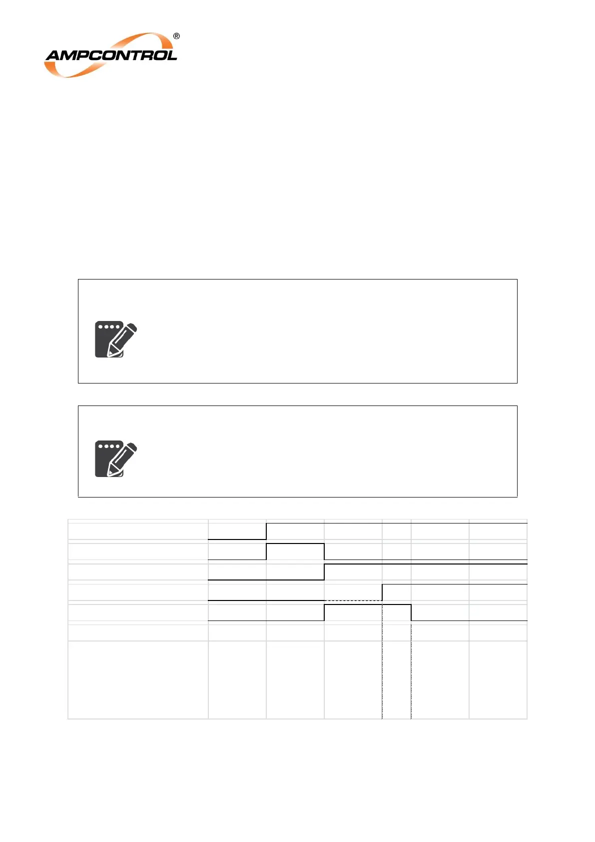
START input
EFLO + HV test
MCR output
MCI input
Startup Transient Mode
Figure 10.3: Transient Overreach Protection Timing Diagram