Installation and Setup
48
Instruction Manual – DXLink™ Twisted Pair Transmitters/Receiver
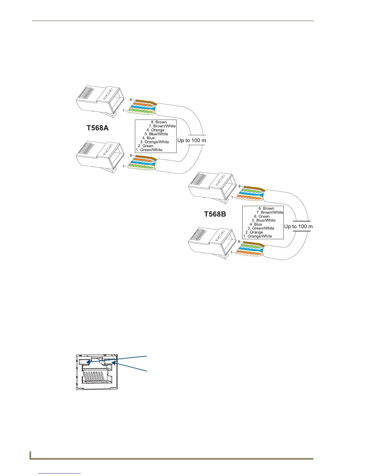
Twisted Pair Cable Pinouts
The pinout in FIG. 26 is for twisted pair cable that connects to the ICS LAN 10/100 connector or to the
DXLink connector on the Transmitters and Receivers.
Use either the T568A or T568B pinout
specification for termination of the twisted pair cable used between the modules in a standalone setup or
between Transmitters and Receivers and an enclosure in a full system.
In a typical installation, the cables should be stretched to their full length between Transmitters and
Receivers and the enclosure or between modules in a standalone system. Service loops or coils of the
cable may reduce the overall cable performance and should be minimized whenever possible.
RJ-45 LEDs
ICS LAN 10/100 Connector LEDs (modules only)
The following information applies to the LEDs on the ICS LAN 10/100 connector on the modules
(FIG. 27). Note that #1 Toggle must be set to ON or ICS LAN functionality will not be provided.
FIG. 26 Twisted pair cable pinouts for Ethernet connectors
Yellow LED
Green LED
ICS LAN 10/100 LEDs
(modules only)
Link/Activity (L/A) Green LED:
On – Link status is active (when
the Ethernet cable is connected
and terminated correctly)
Off – Link status is not active
Speed Status (SPD) Yellow LED:
On – Speed status is 100 Mbps
Off – Speed status is 10 Mbps
FIG. 27 Module ICS LAN 10/100 connector LEDs
RJ-45 Connector LEDs