ADV7511W HARDWARE USER’S GUIDE
Rev.A
Page 30
of 45
Rev A
Figure 14
AES3 Direct Audio
6.1.3.3 Sony/Philips Digital Interface (S/PDIF)
The ADV7511W is capable of accepting two-channel linear pulse code modulation (LPCM) and encoded audio up to a
192KHz sampling rate via the S/PDIF. S/PDIF audio input is selected by setting R0x0A[4] = ‘1’. The ADV7511W is capable of
accepting S/PDIF with or without an MCLK
input. When no MCLK is present the ADV7511W generates its own MCLK.
For timing information see ▶Figure 4.
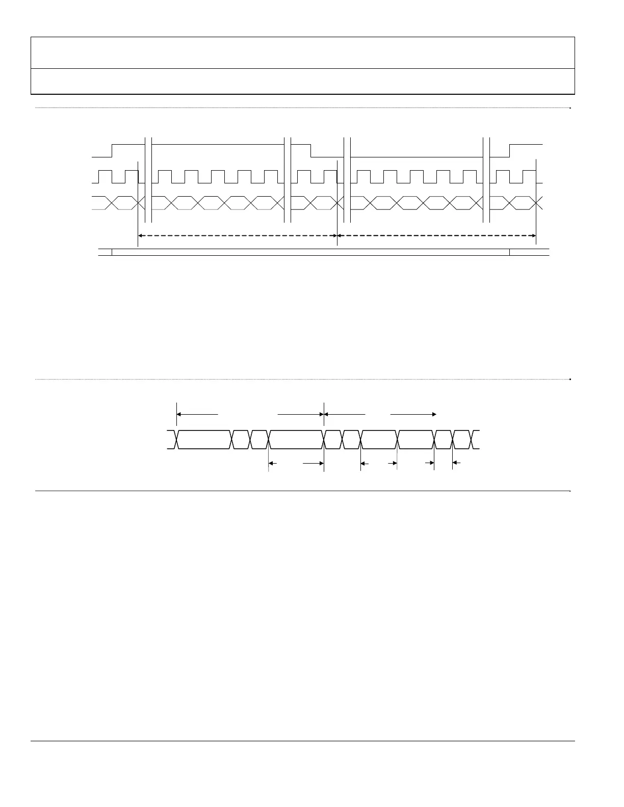
Figure 15
S/PDIF Data Timing
6.1.3.4 HBR Audio
High Bit-Rate audio uses the HBR audio packets to transfer compressed data at rates greater than 6.144Mbps across
the TMDS link. For additional information, refer to IEC61937.
6.1.4
Hot Plug Detect (HPD) pin
The Hot Plug Detect (HPD) pin is an input which detects if a DVI or HDMI sink is connected. If the voltage on HPD
is greater than 1.2V, then the ADV7511W considers an HDMI/DVI sink is connected. If the voltage is below 1.2V,
then the ADV7511W considers no sink is connected. The HPD must be connected to the HDMI connector. A 10KΩ
(+/-10%) pull down resistor to ground is recommended: this ensures that 0V is present on the HPD pin when no sink
is connected.
6.1.5
Power Down / I2C Address (PD/AD)
The Power Down / Address (PD/AD) input pin can be connected to GND or AVDD (through a 2KΩ (+/-10%) resistor
or a control signal). The device address and power down polarity are set by the state of the PD/AD pin when the
ADV7511W supplies are applied. For example, if the PD/AD pin is low (when the supplies are turned on) then the
I2S[3:0]
LRCLK
SCLK
Channel A Channel B
LSB
LSB
32 Clock Slots 32 Clock Slots
MSB
MSB V
U
C
P
V
UCP
Frame n + 1Frame n
AES3 Direct Audio
R0x0C[1:0] = ‘11’
Sync Impulse
S/PDIF
Data
1.5*T
MCLK
T
MCLK
0.5*T
MCLK
 Loading...