ADV7511W HARDWARE USER’S GUIDE
Rev. A
Page 43
of 45
Rev A
7.6
Current Reference Pin: R_EXT
The external reference resistor should be connected between the R_EXT pin and ground with as short a trace as
possible. The external reference resistor must have a value of 887 Ohms (+/-1% tolerance). It is strongly recommended
to avoid running any high-speed AC or noisy signals next to the R_EXT line or close to it. Specifically it is
recommended that no switching signals – such as LRCLK (including vias) be routed close to R_EXT pin (14). Low-
level TMDS switching noise should have minimal impact on R_EXT. Therefore, it is acceptable to place a via for
R_EXT near TMDS signals such as TX0+ and TX0-
7.7
CEC Implementation
An external clock is required to drive the CEC_CLK input pin. Default frequency is 12MHz, but any clock between
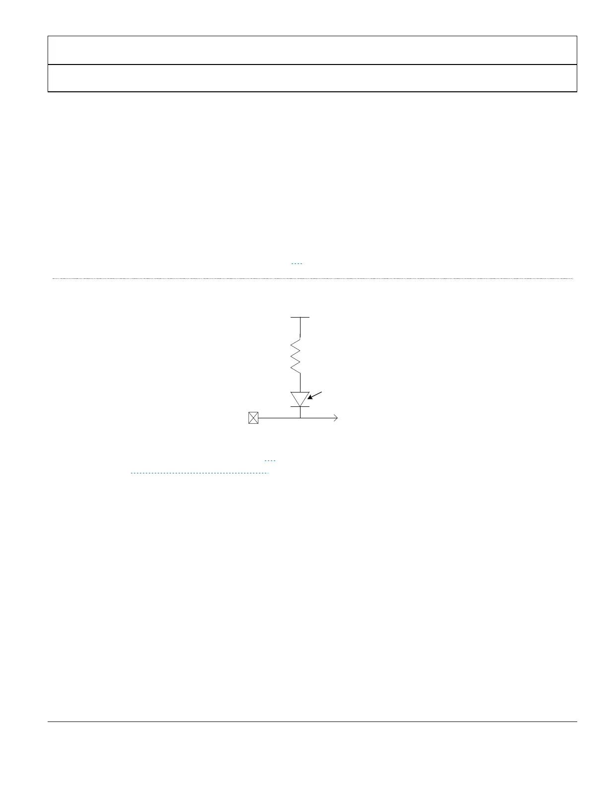
3MHz and 100MHz (+/-2%) can be used. Figure 24
illustrates the recommended connection to the CEC line.
Figure 24
CEC external connection
An example schematic is shown in Figure 25
. For a complete set of reference schematics and PCB layout example,
contact ATV_VideoTX_apps@analog.com
.
CEC_IO
HDMI
Connector
27K
ohms
VDD=3.3V
leakage < 1.8uA
 Loading...