ADV7511W HARDWARE USER’S GUIDE
Rev. A
Page 17
of 45
Rev A
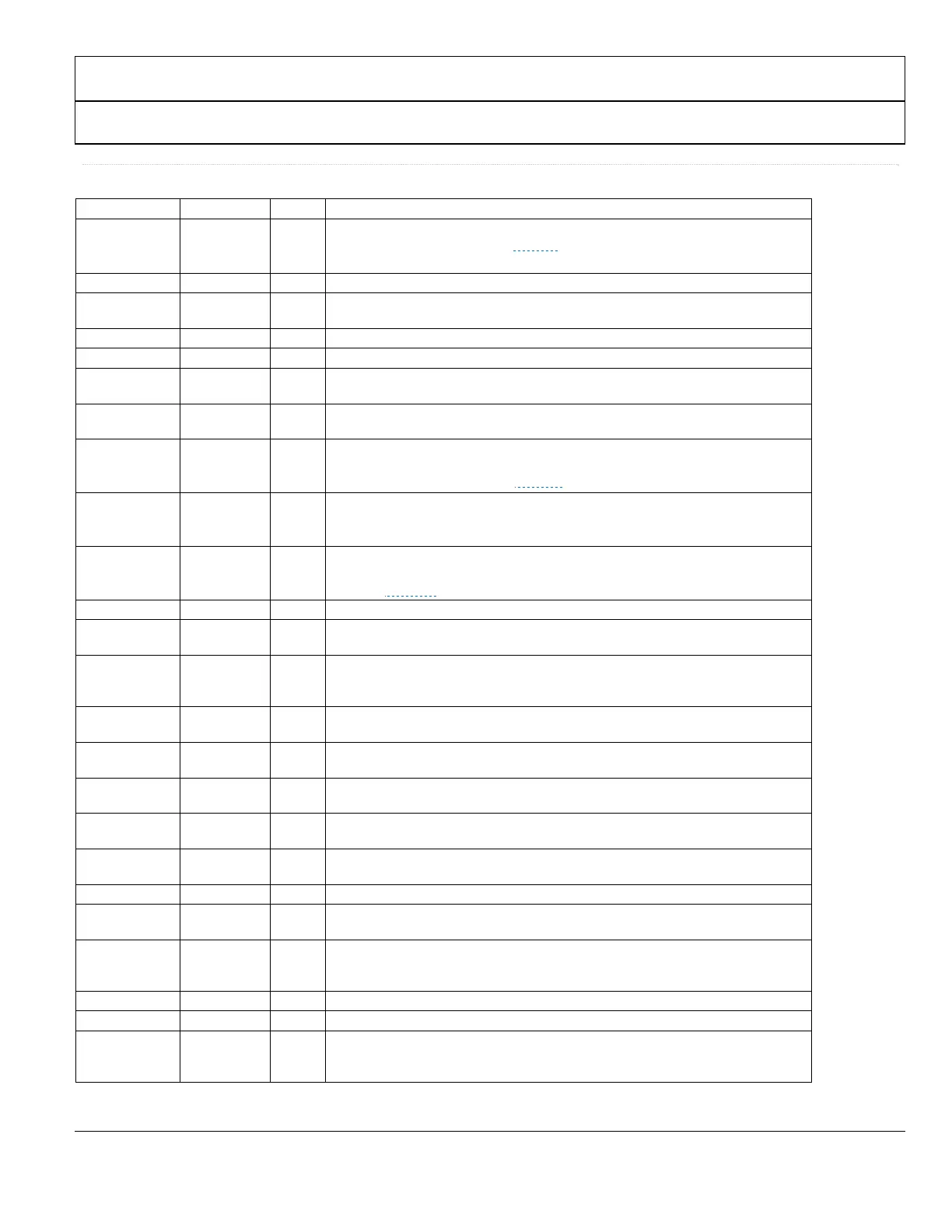
Table 3
Complete Pinout List ADV7511W
Pin No. Mnemonic Type
1
Description
37 to 44,
45 to 50, 52, 54
55 to 62
D[23:0] I
Video Data Input. Digital input in RGB or YCbCr format. Supports typical CMOS logic
levels from1.8V up to 3.3V. See ▶Figure 2
for timing details.
53 CLK I Video Clock Input. Supports typical CMOS logic levels from 1.8V up to 3.3V.
63 DE I
Data Enable signal input for Digital Video. Supports typical CMOS logic levels from
1.8V up to 3.3V.
64 HSYNC I Horizontal Sync Input. Supports typical CMOS logic levels from 1.8V up to 3.3V.
2 VSYNC I Vertical Sync Input. Supports typical CMOS logic levels from 1.8V up to 3.3V.
14 R_EXT I
Sets internal reference currents. Place 887 Ω resistor (1% tolerance) between this
pin and ground.
30 HPD I
Hot Plug Detect signal input. This indicates to the interface whether the sink is
connected. 1.8V to 5.0 V CMOS logic level.
3 S/PDIF I
S/PDIF (Sony/Philips Digital Interface) Audio Input. This pin is typically used as
the audio input from a Sony/Philips digital interface. Supports typical CMOS logic
levels from 1.8V up to 3.3V. See ▶
Figure 4 for timing details.
4 MCLK I
MCLK input for SPDIF and I2S audio. (See ▷ADV7511 Programming Guide for
details on the register bit that controls this). .Supports typical CMOS logic levels
from 1.8V up to 3.3V.
8-5 I
2
S[3:0] I
I
2
S Audio Data Inputs. These represent the eight channels of audio (two per
input) available through I
2
S. Supports typical CMOS logic levels from 1.8V up to
3.3V. See Figure 3 for timing details.
9 SCLK I I
2
S Audio Clock input. Supports typical CMOS logic levels from 1.8V up to 3.3V.
10 LRCLK I
Left/Right Channel signal input. Supports typical CMOS logic levels from1.8V up to
3.3V.
22 PD/AD I
Power-Down Control and I
2
C Address Selection. The I
2
C address and the PD
polarity are set by the PD/AD pin state when the supplies are applied to the
ADV7511W. Supports typical CMOS logic levels from 1.8V up to 3.3V.
17, 18 TxC−/TxC+ O
Differential TMDS Clock Output. Differential clock output at pixel clock rate;
TMDS logic level.
26, 27 Tx2−/Tx2+ O
Differential TMDS Output Channel 2. Differential output of the red data at 10×
the pixel clock rate; TMDS logic level.
23, 24 Tx1−/Tx1+ O
Differential TMDS Output Channel 1. Differential output of the green data at 10×
the pixel clock rate; TMDS logic level.
20, 21 Tx0−/Tx0+ O
Differential TMDS Output Channel 0. Differential output of the blue data at 10×
the pixel clock rate; TMDS logic level.
28 INT O
Interrupt signal output. CMOS logic level. A 2 kΩ pull-up resistor (10%) to
interrupt the microcontroller IO supply is recommended.
15, 19, 25 AVDD P 1.8V Power Supply for TMDS Outputs.
1, 11, 31, 51 DVDD P
1.8V Power Supply for Digital and I/O Power Supply. These pins supply power to
the digital logic and I/Os. They should be filtered and as quiet as possible.
12 PVDD P
1.8V PLL Power Supply. The most sensitive portion of the ADV7511W is the clock
generation circuitry. This pin provide power to the PLL clock. The designer
should provide quiet, noise-free power to these pins.
13 BGVDD P Band Gap Vdd.
29 DVDD_3V P 3.3V Power Supply.
PAD GND P
Ground. The ground return for all circuitry on-chip. It is recommended that the
ADV7511W be assembled on a single, solid ground plane with careful attention
given to ground current paths.
 Loading...