Medium-consistency pump MC
STANDARD, C-01-000000
Rev. 0, 2010.02.09 MAINTENANCE Kap.7 , Seite 16 of 22
GRZ-2698573-v1-Maintenance.FM
Installation of the
impeller (230.1)
and fluidisator
(230.2)
Preliminary requirements:
• Pump shaft, impeller and fluidisator comply with the requirements in
terms of measuring accuracy, roundness and true running.
Step Activity
1 Clean pump shaft (211), fluidisator (230.2) and impeller (230.1),
particularly the fitting surfaces of the impeller hub and the
pump shaft.
2 Mount the impeller and the fluidisator on the pump shaft and
tighten the screw (
901.2) according to Tab. 7-5 (Torques).
3 The gap between the impeller (230.1) and the casing cover
(
161) should be 1 +/- 0,3 mm (Fig. 7-8). This is obtained by
adding spacer plates (551.2) between impeller and mechanical
seal (
433)
The gap between the impeller (230.1) and the front lining
(
135.1) should be 1 +/- 0,3 mm (Fig. 7-8). This is obtained by
adding more seals (551.2) between the suction flange (153)
and the front lining (
135.1)
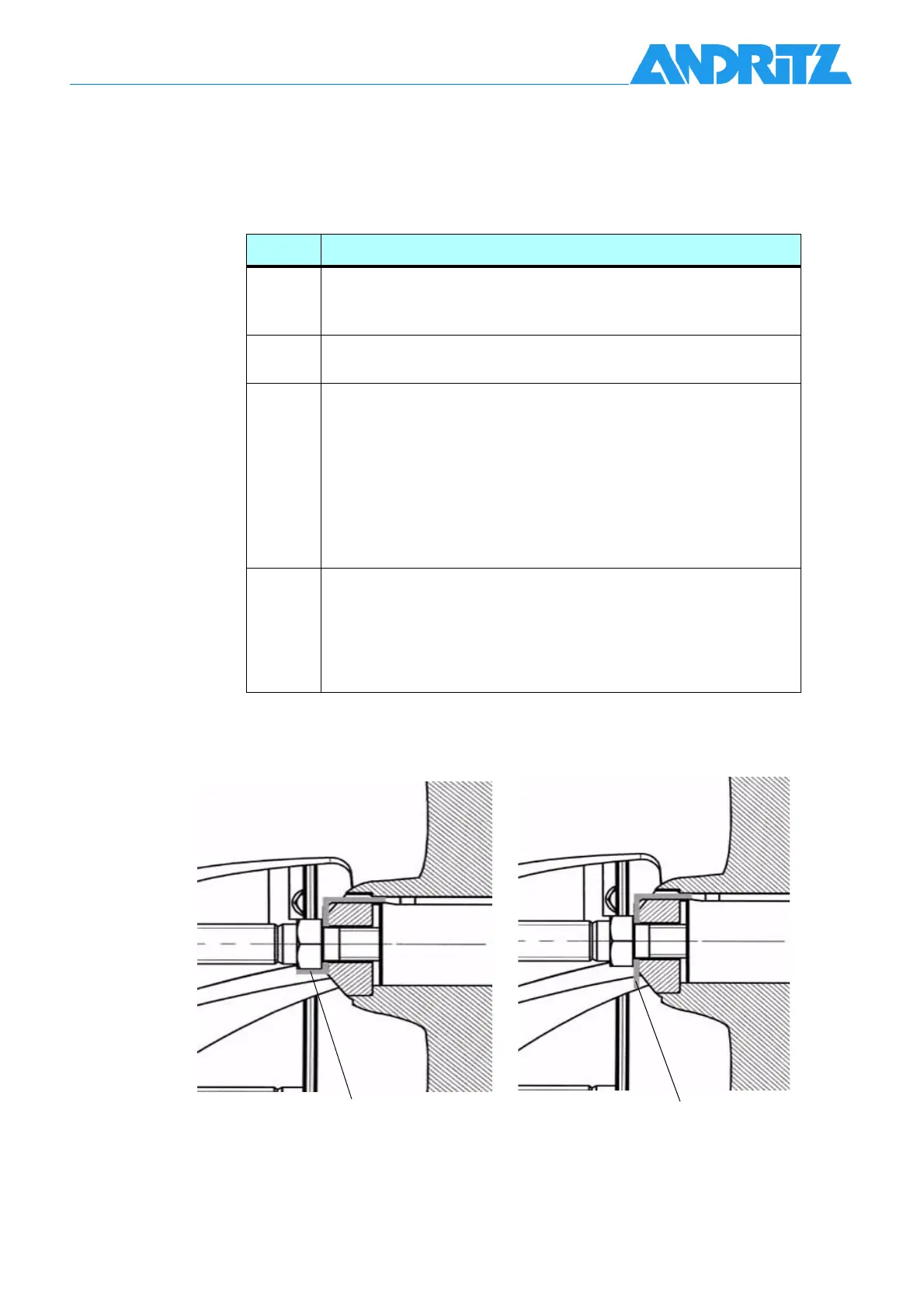
4 Tighten hexagon head screw (901.2) with torques according to
Tab. 7-5 and lock the screw (901.2) by turning the locking plate
(931.2) in a horizontal position as shown in Abb. 7-9.
CAUTION:
For re-assembling always use a new locking plate (931.2)
Tab. 7-14 Installation of the impeller
Abb. 7-9 Locking the screw (901.2) by adjusting locking plate (931.1)
locked
unlocked