Test Port Extension Cable (Figure 2-8) prior to press-
ing ENTER.
After each selection, the message “Measuring
OPEN,” “Measuring SHORT,” or “Measuring
LOAD” appears while the measurement is in prog-
ress.
For WAVEGUIDE:
Follow the ensuing “Connect SHORT 1, Press
ENTER,” “Connect SHORT 2, Press ENTER,”
and “Connect LOAD, Press ENTER” instructions
that appear in the message area. Connect the repec-
tive Short 1, Short 2, and Load components to the
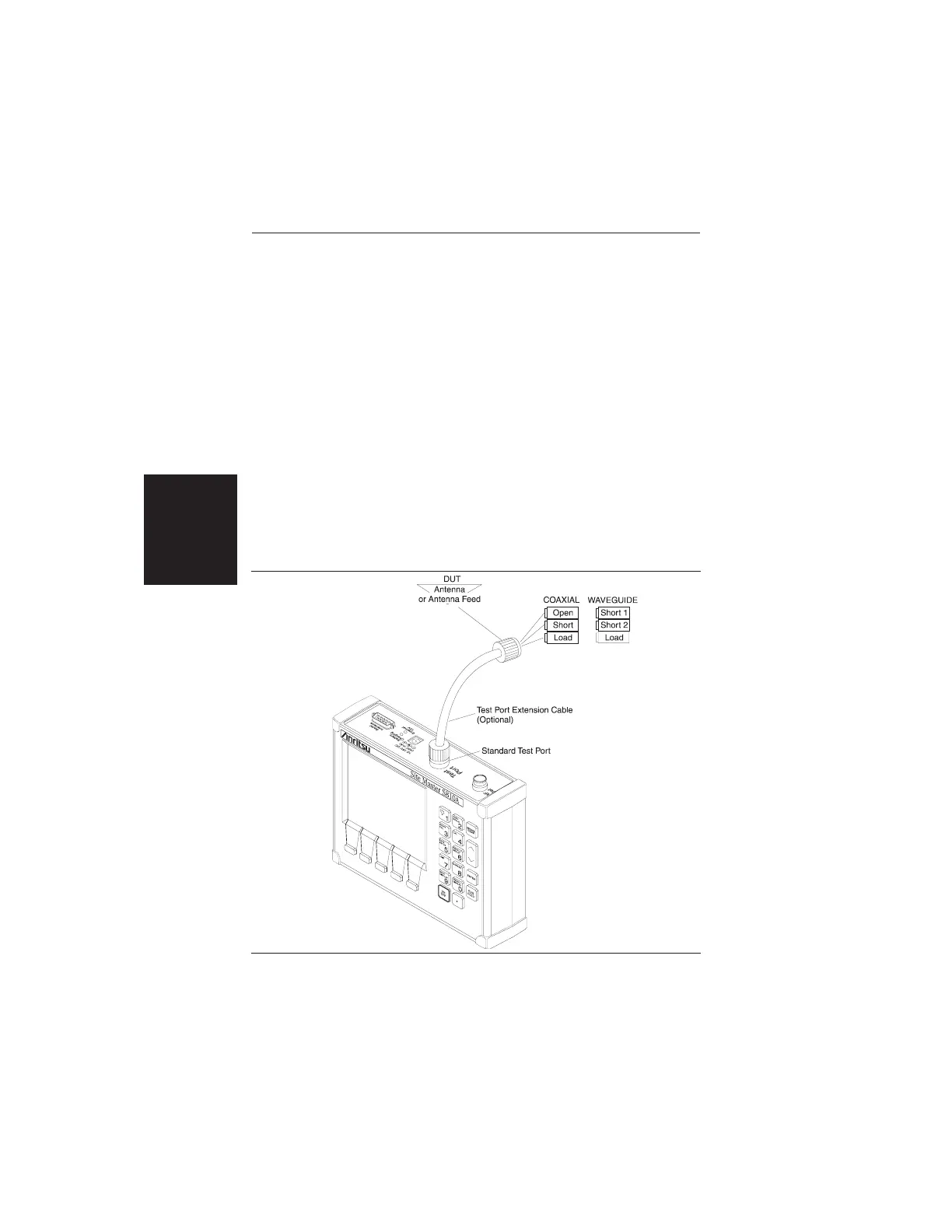
end of the Test Port Extension Cable (Figure 2-8)
prior to pressing ENTER.
2-26
Chapter 2 Operation
Figure 2-8. One-Port Measurement/Calibration Test Setup