Host Interface 8 (114)
3 Host Interface
This chapter describes the low level properties of the Anybus CompactCom interface
3.1 Overview
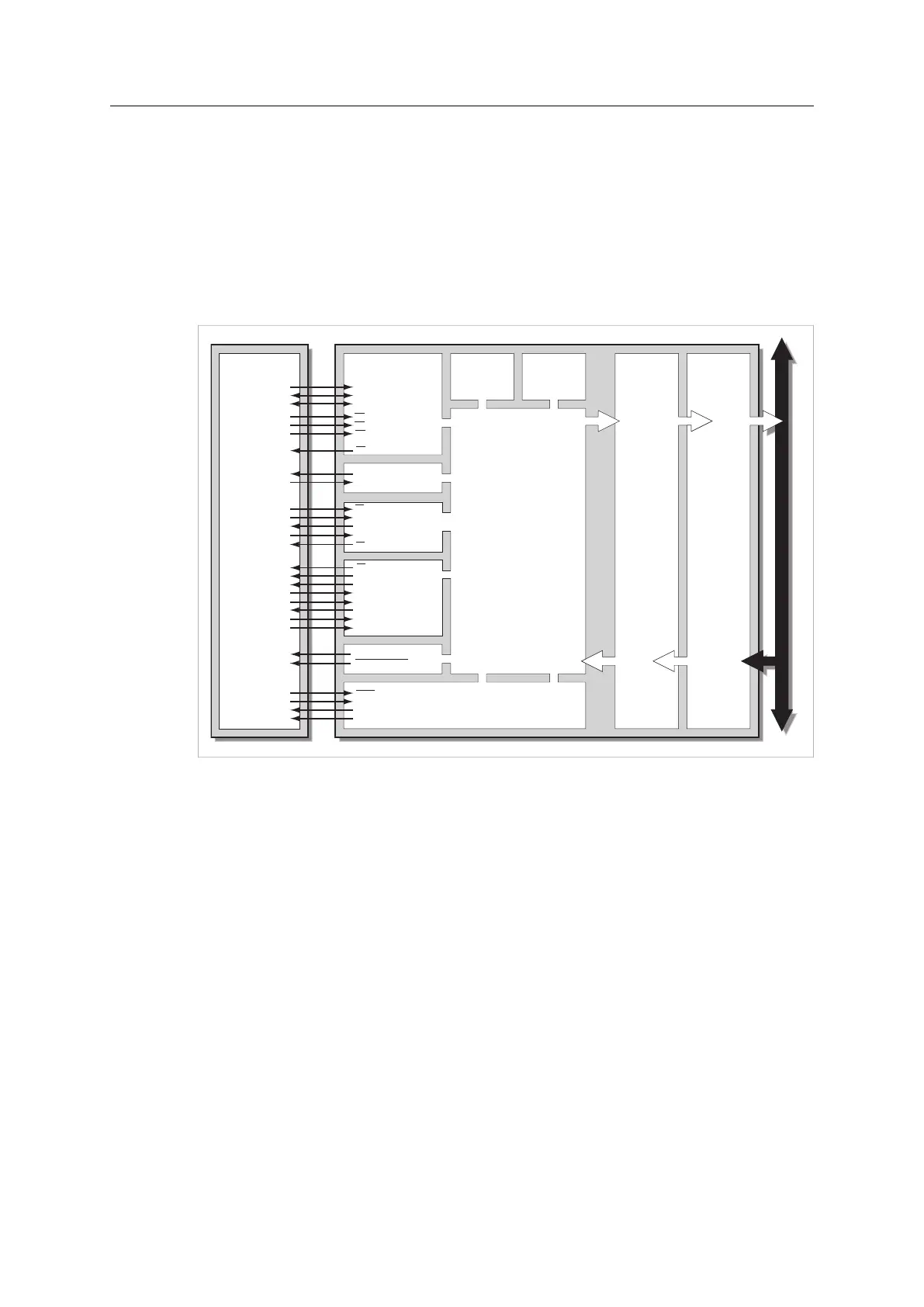
The Anybus CompactCom has five different host communication interfaces, corresponding to
different operating modes. The figure below illustrates the basic properties of these interfaces
as well as various I/O and control signals, and how they relate to the host application.
Host
CPU
Flash
Parallel Interface,
8-bit or 16-bit
Serial Interface
LED I/F
or RMII
RAM
A0 ... A13
Tx
Rx
LED[1A, 1B, 2A, 2B]
LED[3A, 3B, 4A, 4B]
RESET
OM[0...3]
MI[0...1]
MD[0...1]
D0 ... D7
CS
OE
WE
IRQ
Physical Interface
Anybus
CPU
Network
Communications Controller
SPI
Shift Registers
SS
SCLK
MISO
MOSI
LD
SCLK
DO
DI
CT
PA
DIP1[0...7]
DIP2[0...7]
IRQ
D8 ... D15
Fig. 1
Please note that only one communication interface at a time is available. Which one is decided
at startup.
3.1.1 Parallel Interface, 8-bit or 16-bit
From an external point of view, the parallel interface is a common 8-bit or 16-bit parallel slave
port interface, which can easily be incorporated into any microprocessor based system that has
an external address/data bus. Generally, implementing this type of interface is comparable to
implementing an 8-bit or 16-bit wide SRAM. Additionally, the parallel interface features an
interrupt request line, allowing the host application to service the module only when actually
needed.
3.1.2 SPI
The Serial Peripheral Interface (SPI) is a synchronous serial link. It operates in full duplex mode
and devices communicate in master/slave mode where the Anybus CompactCom modules
always act as slaves. The interface can provide much higher performance than the serial
interface, but not as high as the parallel interface.
Anybus
®
CompactCom
™
M40 Hardware Design Guide HMSI-216-126 EN 2.6