Appendix A: Implementation Examples 48 (114)
A.7 Network Status LED Outputs (LED[1A...4B])
The LED[1A....4B] outputs can be used to relay the network status LEDs to elsewhere on the
host application. This is possible in all modes except 16-bit parallel mode, where these pins are
used for data (D8...D15).
Note that it is the responsibility of the host application to ensure that each LED output is
connected to a LED of the correct color (on active modules, it is possible to retrieve this
information from the LED status register or from the Anybus Object (01h); consult the Anybus
CompactCom 40 Software Design Guide for more information). For more information, see LED
Interface / D8–D15 (Data Bus), p. 13.
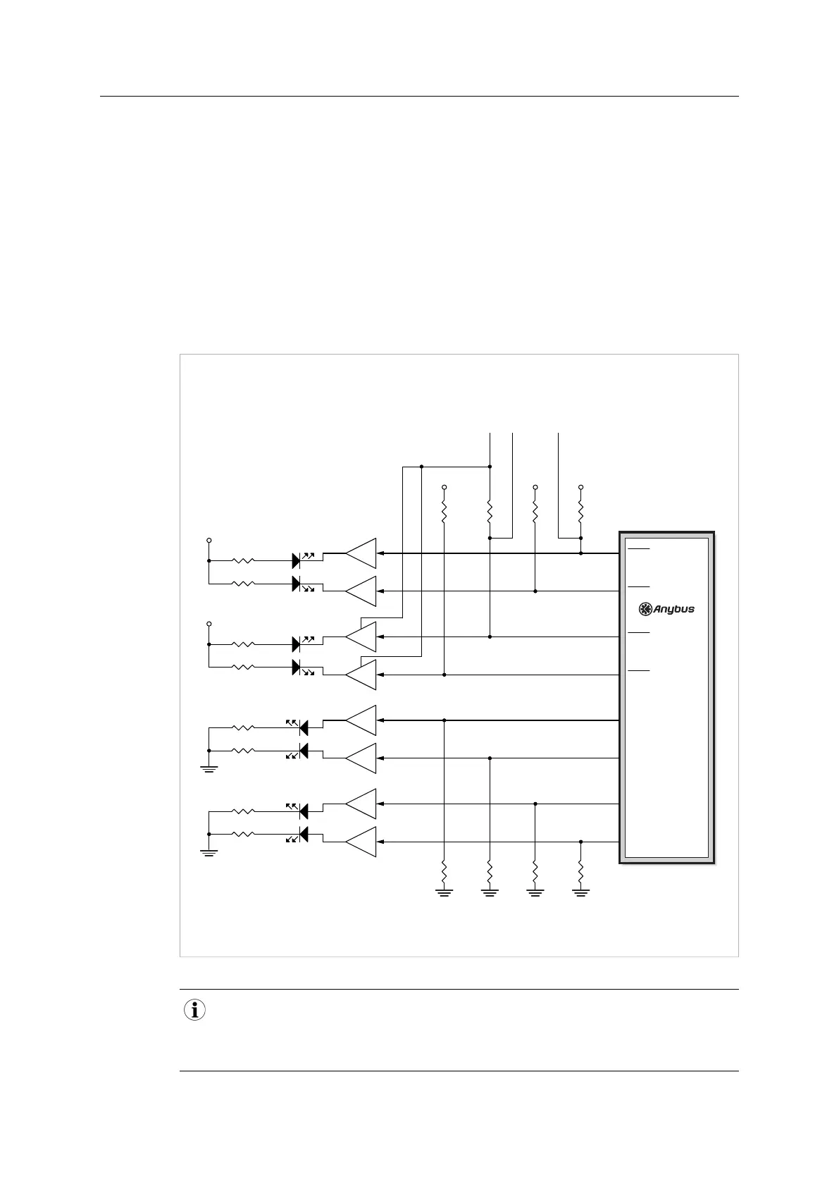
The outputs are unbuffered, and are not recommended for driving LEDs directly. Please consult
the image below for guidelines on how to connect the LED outputs.
3V33V3
3V3
3V3
3V3
LED1A
LED1B
LED2A
LED2B
LED3A
LED3B
LED4A
LED4B
CA
RTS
ACTIVE/PASSIVE*
*By connecting this signal to Ground, this design can be used to support Anybus CompactCom passive modules.
Fig. 26
These pins can not be used for LEDs in 16-bit parallel mode, as the pins in that case are used for
data.
This solution can be used to support Anybus CompactCom passive modules. Please verify that
the rest of the application is correctly designed for passive modules.
Anybus
®
CompactCom
™
M40 Hardware Design Guide HMSI-216-126 EN 2.6