Appendix A: Implementation Examples 46 (114)
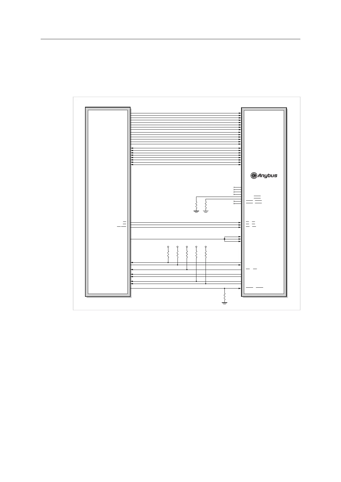
A.5 8–bit Parallel
This design for 8-bit parallel mode, including firmware update (via UART), can be used for both
M30 and M40.
Firmware update for a M40 series module is preferably done using the File System Interface
Object, see Anybus CompactCom 40 Software Design Guide.
Host Application
CPU (3.3V)
3V33V3
3V3
3V33V3
A8
A9
A10
A11
A12
A13
CS
RD
WR/WR0
Rx
Tx
GPIO5
GPIO6
GPIO7
GPIO8
GPIO9
GPIO10
GPIO4
A8 / A8
A9 / A9
A10 / A10
A11 / A11
A12 / A12
A13 / A13
LED1B / LED1B
LED1A / LED1A
LED2B / LED2B
LED2A / LED2A
GIP0 / LED3B
GIP1 / LED3A
GOP0 / LED4B
GOP1 / LED4A
CS / CS
OE / OE
WE / WE
OM0 / OM0
OM1 / OM1
OM2 / OM2
Tx / Tx/OM3
Rx / Rx
IRQ / IRQ
RESET / RESET
MI0 / MI0/SYNC
MI1 / MI1
MD0 / MD0
MD1 / MD1
A0 / A0
A1 / A1
A2 / A2
A3 / A3
A4 / A4
A5 / A5
A6 / A6
A7 / A7
A0
A1
A2
A3
A4
A5
A6
A7
D0 / D0
D1 / D1
D2 / D2
D3 / D3
D4 / D4
D5 / D5
D6 / D6
D7 / D7
D0
D1
D2
D3
D4
D5
D6
D7
M30 pinning / M40 pinning
Fig. 24
If LEDs are to be used in the host application, please refer to Network Status LED Outputs
(LED[1A...4B]), p. 48, for guidelines on how to connect the LED outputs.
The pull-down resistors on LED3A and LED3B make it possible to support Anybus
CompactCom passive modules.
Anybus
®
CompactCom
™
M40 Hardware Design Guide HMSI-216-126 EN 2.6