Host Interface 30 (114)
3.5 Stand-alone Shift Register
3.5.1 General Information
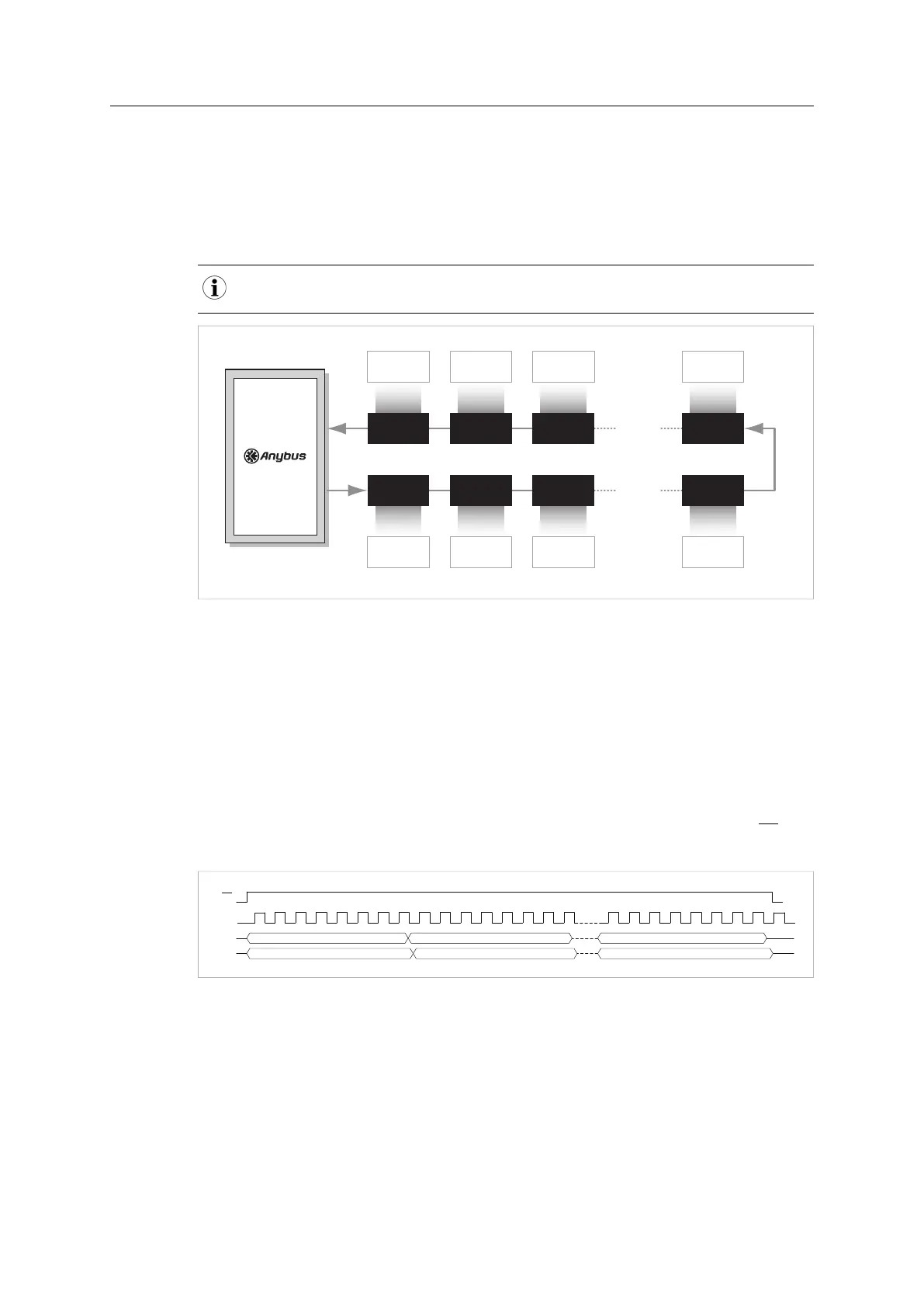
In this mode the Anybus CompactCom M40 operates stand-alone, with no host processor.
Process data is communicated to shift registers on the host. The Anybus CompactCom M40
supports up to 32 registers in each direction, for a total of 256 bits of data.
The PROFIBUS version of the Anybus CompactCom 40 supports up to 24 registers in each
direction, for a total of 192 bits of data.
INPUT SHIFT
REGISTER 32
Input Byte 31Input Byte n-1
Output Byte 31Output Byte n-1
OUTPUT SHIFT
REGISTER 32
INPUT SHIFT
REGISTER 1
INPUT SHIFT
REGISTER 2
INPUT SHIFT
REGISTER 3
OUTPUT SHIFT
REGISTER 1
OUTPUT SHIFT
REGISTER 2
OUTPUT SHIFT
REGISTER 3
INPUT SHIFT
REGISTER n
Input Byte 0
Input Byte 1 Input Byte 2
Output Byte 0 Output Byte 1 Output Byte 2
OUTPUT SHIFT
REGISTER n
ADI #1 ADI #2
ADI #3
ADI #32
ADI #64 ADI #63
ADI #62
ADI #33
Fig. 15
Even though the Anybus CompactCom M40 operates stand-alone, it is still possible to set host
application attributes, via the use of the virtual attributes list. Some attributes are mandatory to
implement in order to pass conformance tests
See the Virtual Attributes section in the Anybus CompactCom 40 Software Design Guide for
more information.
The Anybus CompactCom M40 will automatically detect the number of connected input and
output shift registers. Every shift register will be represented by one UINT8 ADI. The input ADIs
will be named “Input 0”, “Input 1”, etc. The output ADIs will be named “Output 0”, “Output 1”, etc.
Bits are clocked out/in MSB first, on the positive side of CLK. An active low load signal (LD)
loads all shift registers before and after a transfer.
LD
SCLK
Input byte 0
DO
DI
Output byte 31 Output byte 30
Input byte 1
Output byte 0
Input byte 31
Fig. 16
A fifth signal, PA, is high when the module is in active state, and low when the module is not.
This signal can be used by the application to clear/set the output shift registers to default values
when the module is not in active state.
Anybus
®
CompactCom
™
M40 Hardware Design Guide HMSI-216-126 EN 2.6