Appendix E: Anybus CompactCom 40 without Housing 100 (114)
E.4 Host Connectors
The following connectors have been found to be compatible with the mounting kit.
Manufacturer Part No. Comment Web
Samtec HPT-125-01-L-D-RA
(recommended)
Through hole mounted
www.
samtec.
com
3M N7E50-D516PG-30 Surface mounted www.3m.
com
E.5 Height Restrictions
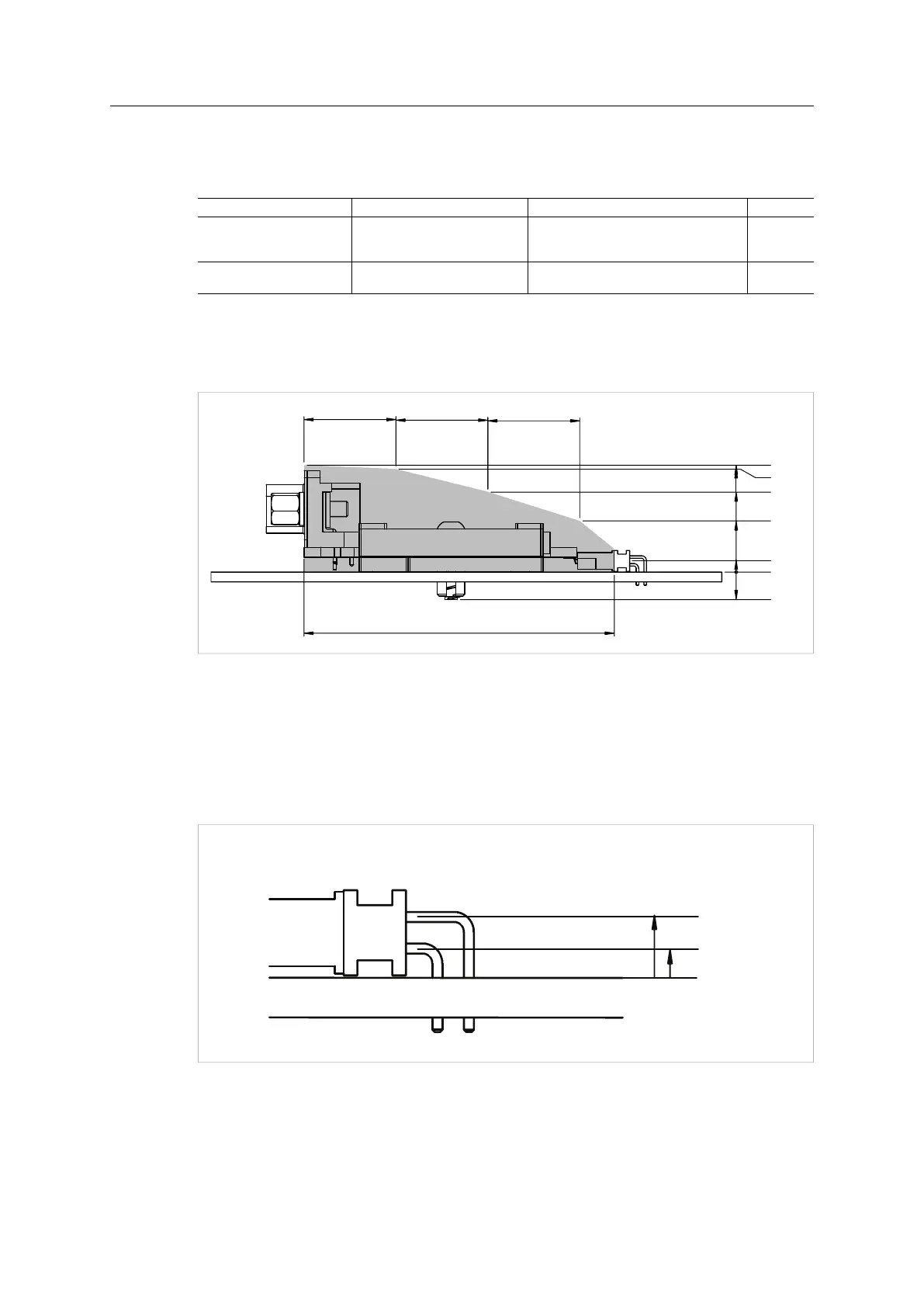
All dimensions are in millimeters
50.7
17.4
16.8
13
8.3
4.5
0
15 15 15
*
*See note 1 below
Fig. 54
To ensure stable connection to FE, use a connector that conforms to the distances from the
PCB to the pins of the host connector, that are recommended in the picture. Tolerance (0.35
mm, -0.05 mm).
The gray area in the figure above specifies the maximum height occupied by onboard
components of the Anybus module. To ensure isolation, it is recommended to add an additional
2.5 mm on top of these dimensions.
Fig. 55
Anybus
®
CompactCom
™
M40 Hardware Design Guide HMSI-216-126 EN 2.6