Appendix A: Implementation Examples 47 (114)
A.6 SPI and Serial
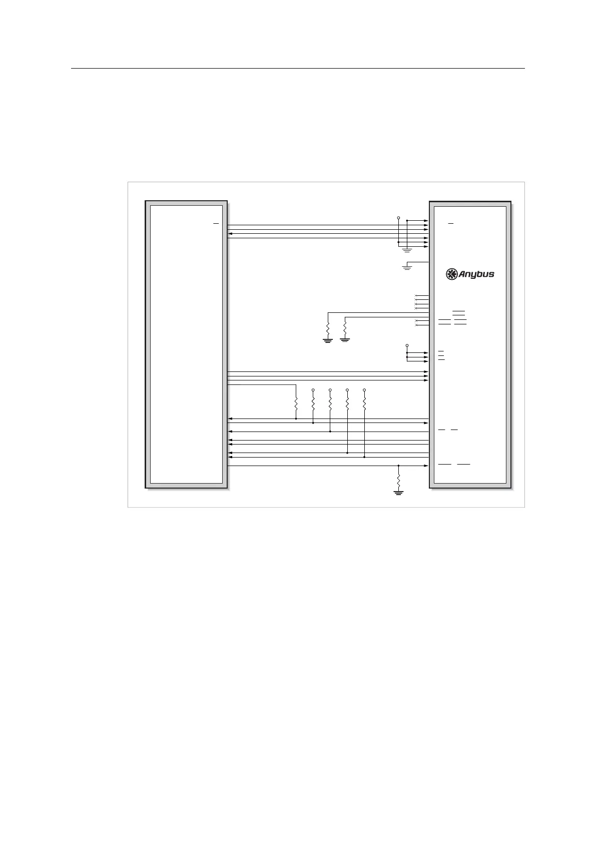
When using M30, the serial interface will be available with this design, as well as firmware
update (using a UART). If the M30 is exchanged for a M40 the SPI interface will also be
available.
Firmware update for a M40 series module is preferably done using the File System Interface
Object, see Anybus CompactCom 40 Software Design Guide.
Host Application
CPU (3.3V)
3V3
3V3
3V3
3V3
3V33V3
[A0... A7] / (not used)
A8 / SS
A9 / SCLK
A10 / MISO
A11 / MOSI
A12 / (not used)
A13 / (not used)
[D0... D7] / (not used)
LED1B / LED1B
LED1A / LED1A
LED2B / LED2B
LED2A / LED2A
GIP0 / LED3B
GIP1 / LED3A
GOP0 / LED4B
GOP1 / LED4A
CS / (not used)
OE / (not used)
WE / (not used)
OM0 / OM0
OM1 / OM1
OM2 / OM2
Tx / Tx/OM3
Rx / Rx
IRQ / IRQ
RESET / RESET
MI0 / MI0/SYNC
MI1 / MI1
MD0 / MD0
MD1 / MD1
SS
SCLK
MISO
MOSI
Rx
Tx
GPIO1
GPIO2
GPIO3
GPIO4
GPIO5
GPIO6
GPIO7
GPIO8
GPIO9
GPIO10
M30 pinning / M40 pinning
Fig. 25
If LEDs are to be used in the host application, please refer to Network Status LED Outputs
(LED[1A...4B]), p. 48, for guidelines on how to connect the LED outputs.
In serial mode, The pull-down resistors on LED3A and LED3B make it possible to support
Anybus CompactCom passive modules.
Anybus
®
CompactCom
™
M40 Hardware Design Guide HMSI-216-126 EN 2.6