Host Interface 10 (114)
3.2 Connector
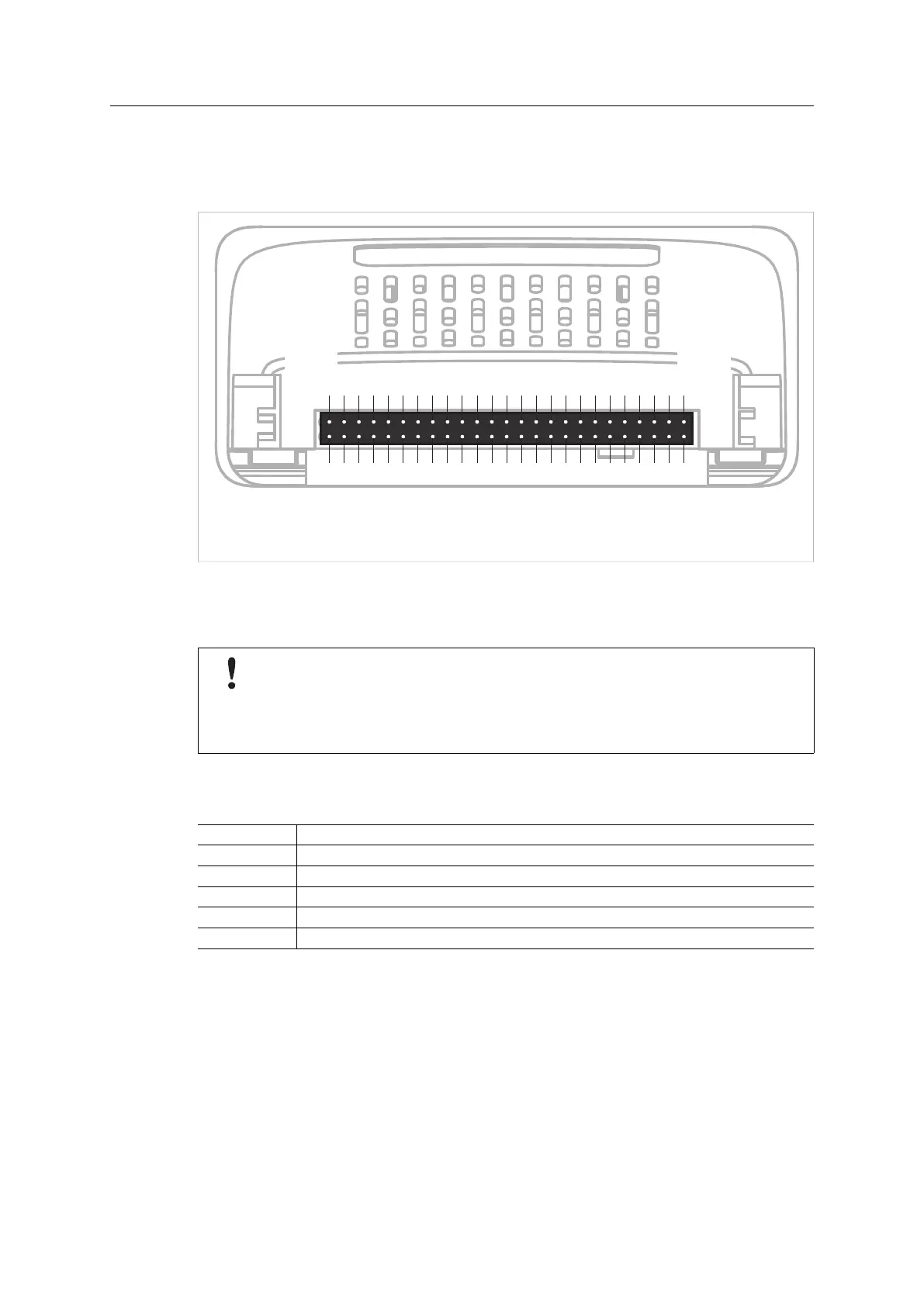
The Anybus CompactCom uses a 50–pin CompactFlash
™
style connector. The pinning is seen
form the host application side of the Anybus CompactCom module
50
(GND)
26
(MD0)
(MD1)
25
(GND)
1
Fig. 2
See .Application Connector Pin Overview, p. 11 for information on how each pin is used in the
different modes.
The host interface is not pin compatible with the CompactFlash
™
standard. Also,
prior to exchanging a module, power should be turned off or the MD (module
detection signals should be used to shut down communication and power when the
module is removed. Failure to observe this may cause damage to the host product
and/or the Anybus CompactCom module.
The pin types of the host interface connector are defined in the table below. The pin type may
be different depending on which mode is used.
Pin type Definition
I Input
O Output
I/O Input/Output (bidirectional)
OD Open Drain
Power Pin connected directly to module power supply, GND or 3V3
Anybus
®
CompactCom
™
M40 Hardware Design Guide HMSI-216-126 EN 2.6