Appendix A: Implementation Examples 44 (114)
A.3 Serial and 16–bit Parallel
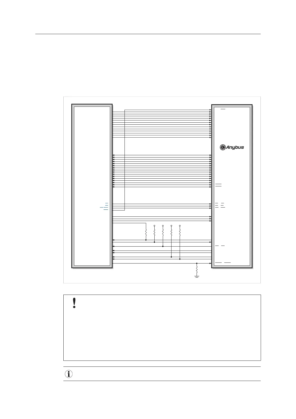
The example in the figure below shows an implementation with serial communication and
firmware update (via UART). An Anybus CompactCom 30, connected as shown, can thus be
used in serial mode and is prepared for firmware update via the UART. Exchanging the M30 for
the M40 will also give access to 16-bit parallel mode.
Firmware update for an M40 series module is preferably done using the File System Interface
Object, see Anybus CompactCom 40 Software Design Guide.
Host Application
CPU (3.3V)
3V3
3V3
3V3
3V3
A0 / WEH
A8 / A8
A9 / A9
A10 / A10
A11 / A11
A12 / A12
A13 / A13
LED1B / D8
LED1A / D9
LED2B / D10
LED2A / D11
GIP0 / D12
GIP1 / D13
GOP0 / D14
GOP1 / D15
CS / CS
OE / OE
WE / WEL
OM0 / OM0
OM1 / OM1
OM2 / OM2
Tx / Tx/OM3
Rx / Rx
IRQ / IRQ
RESET / RESET
MI0 / MI0/SYNC
MI1 / MI1
MD0 / MD0
MD1 / MD1
A8
A9
A10
A11
A12
A13
D8
D9
D10
D11
D12
D13
D14
D15
CS
RD
WR/WR0
WR1
Rx
Tx
GPIO5
GPIO6
GPIO7
GPIO8
GPIO9
GPIO10
GPIO1
GPIO2
GPIO3
GPIO4
D0 / D0
D1 / D1
D2 / D2
D3 / D3
D4 / D4
D5 / D5
D6 / D6
D7 / D7
D0
D1
D2
D3
D4
D5
D6
D7
A1 / A1
A2 / A2
A3 / A3
A4 / A4
A5 / A5
A6 / A6
A7 / A7
A1
A2
A3
A4
A5
A6
A7
M30 pinning / M40 pinning
Fig. 22
To prevent damage to the host processor, as well as the Anybus CompactCom M30
LED outputs, the host processor must disable data inputs/outputs D8 - D15, i.e.
these pins must be set to high impedance state, if MI indicates that some other
module than an Anybus CompactCom M40 is inserted. If a CompactCom M30 is
connected, and if the host processor cannot shut off this part of the data bus, the
CompactCom M30 will have to be protected by external circuitry. See example on
next page.
If the host application uses the data bus lines D8 - D15 for any other purpose, e.g.
toward other circuitry, this implementation may cause damage to other components
connected to the data bus.
This implementation does not support Anybus CompactCom passive modules.
Anybus
®
CompactCom
™
M40 Hardware Design Guide HMSI-216-126 EN 2.6