Appendix C: Technical Specification 83 (114)
C.3 Electrical Characteristics
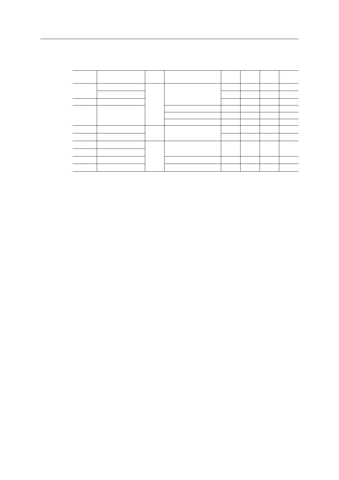
C.3.1 Operating Conditions
Symbol
Parameter
Pin
Types
Conditions Min.
Typ.
Max. Unit
3V3
Supply Voltage (DC)
PWR
-
3.15 3.30 3.45 V
Ripple (AC)
- - ± 100 mV
GND Ground reference 0.00 0.00 0.00 V
I
IN
Current consumption
Class A - - 250 mA
Class B - - 500 mA
Class C - - 1000 mA
V
IH
Input High Voltage I, BI
-
2.0
-
3.45 V
V
IL
Input Low Voltage -0.3
-
0.8 V
I
OH
Current, Output High O, BI
-
-8.0
-
8.0 mA
I
OL
Current, Output Low
V
OH
Output High Voltage I
OH
= -4mA 2.4
- -
V
V
OL
Output Low Voltage I
OL
= 4mA
- -
0.4 V
I= Input, CMOS (3.3V)
O= Output, CMOS (3.3V)
BI= Bidirectional, Tristate
PWR= Power supply inputs
C.3.2 Isolation (Host to Network)
Functional isolation of 500 V AC (1 minute)
C.3.3 Functional Earth & Shielding
All Anybus CompactCom modules features a cable shield filter designed according to each
network standard. To be able to support this, the host application must have a conductive area
connected to functional earth as described in Mechanical Specification, p. 85 (FE Connection
Pad).
HMS cannot guarantee proper EMC behavior unless this requirement is fulfilled.
Anybus
®
CompactCom
™
M40 Hardware Design Guide HMSI-216-126 EN 2.6