Host Interface 29 (114)
3–Wire Mode
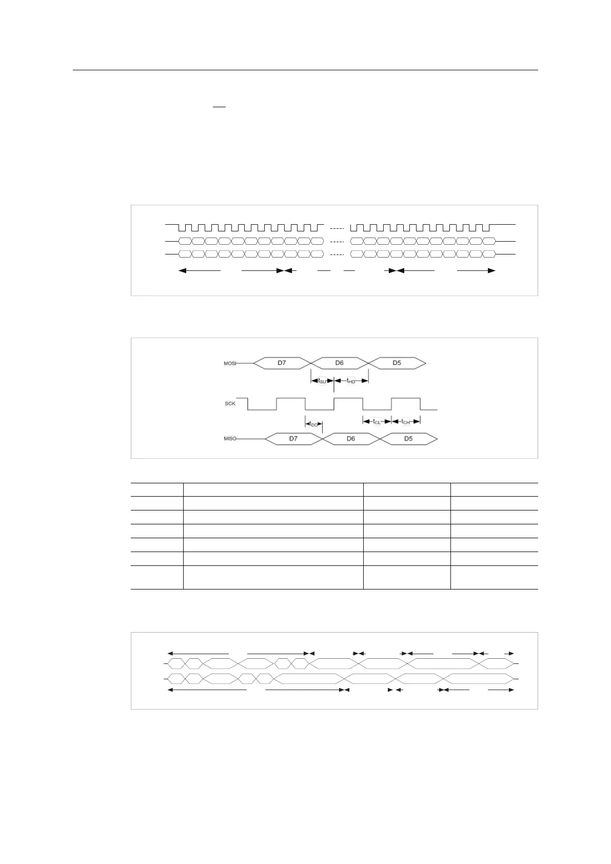
In 3-wire mode the SS signal must be tied low permanently, and the SCLK signal must be idle
high. Multiple SPI slaves on the same bus are not possible in this mode. The module detects
start and stop of a transfer by monitoring SCLK activity.
There must be an idle period of at least 10 µs between two transfers in this mode, and the
SCLK signal must never remain high for more than 5 µs during a transfer.
A 3-wire diagram example.
D0D1D2
D0D1D2
D0D1D2D3D4D5D7 D6
D0D1D2D3D4D5D7 D6
D0D1D2D3D4 D5D7 D6D5D7 D6
D0D1D2D3D4 D5D7 D6D5
SCLK
MOSI
MISO
Byte 0 Byte NByte 1 Byte N-1
D7 D6
Fig. 12
SPI diagram and bit timing for 3-wire mode.
Fig. 13
Item Description Min Value Max Value
tSU MOSI setup before SCK rising edge 10 ns
-
tHD MOSI hold after SCK rising edge 10 ns
-
tDO MISO change after SCK falling edge 0 ns 20 ns
tCL SCK low period 20 ns
-
tCH SCK high period 20 ns
-
tCL+tCH SCK period
Max. frequency supported is 20 MHz.
50 ns
-
SPI Frame Format
MISO
SPI
CTRL
5 Words
Reserv
ed
MSGLEN
APP
STAT
INT
MASK
LEDSTAT
ANB
STAT
SPI
STAT
RdMsgField RdPdField
CRC
MOSI
MSG LEN Words
PD LEN Words
4 Words
2 Words
WrPdField CRC
1 WordMSG LEN Words
PD LEN Words 2 Words
PDLEN
Reserv
ed
Reserv
ed
NETTIME
WrMsgField PADDING
Fig. 14
Most bytes are transmitted with the most significant bit first, but the byte order is little endian.
The least significant byte is transmitted first. The only exception is the CRC32 checksum field
that is transmitted in big endian order.
Anybus
®
CompactCom
™
M40 Hardware Design Guide HMSI-216-126 EN 2.6