Host Interface 28 (114)
4–Wire Mode
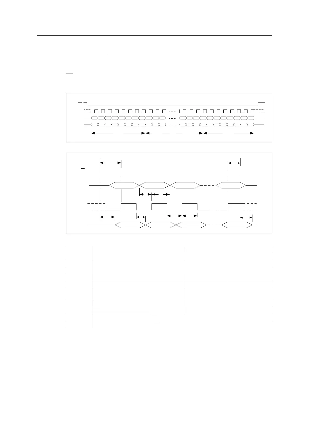
In 4-wire mode the SS signal is used to indicate the start and stop of an SPI transfer. In this
mode the SCLK signal is allowed to be either idle high or idle low. This mode also allows
multiple SPI slaves on the same SPI bus, since Anybus CompactCom MISO is tri-stated when
SS is high.
A 4-wire diagram example:
D0D1D2
D0D1D2
D0D1D2D3D4D5D7 D6
D0D1D2D3D4D5D7 D6
D0D1D2D3D4 D5D7 D6D5D7 D6
D0D1D2D3D4 D5D7 D6D5
SS
SCLK
MOSI
MISO
Byte 0 Byte NByte 1 Byte N-1
D7 D6
Fig. 10
SCLK
MISO
MOSI
D7 D6 D5
D7 D6 D5
t
SU
t
HD
t
DO
t
CL
t
CH
SS
D0
D0
t
CSLZ
t
CSHZ
t
CSS
t
CSH
Fig. 11
Item Description Min Value Max Value
tSU MOSI setup before SCK rising edge 10 ns
-
tHD MOSI hold after SCK rising edge 10 ns
-
tDO MISO change after SCK falling edge 0 ns 20 ns
tCL SCK low period 20 ns
-
tCH SCK high period 20 ns
-
tCL+tCH SCLK period.
Max. frequency supported is 20 MHz.
50 ns
-
tCSS SS setup before first SCLK rising edge. 20ns
-
tCSH SS hold after last SCLK rising edge. 20ns
-
tCSLZ MISO valid after falling edge of SS.
-
20ns
tCSHZ MISO high-Z after rising edge of SS.
-
20ns
Anybus
®
CompactCom
™
M40 Hardware Design Guide HMSI-216-126 EN 2.6