Host Interface 36 (114)
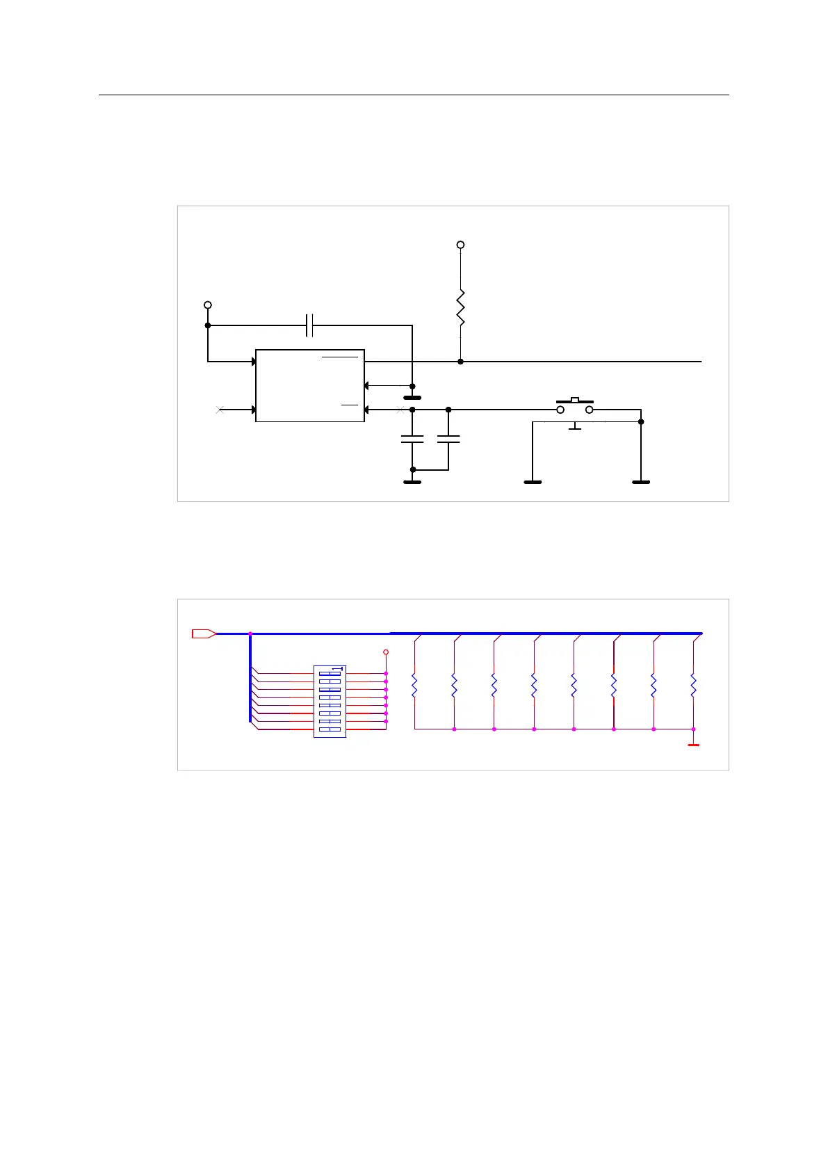
3.5.5 Reset Circuit Example
The reset circuit example in the figure, is a common 3.3 V supervisor. The main usage is to
obtain a defined reset release delay after the voltage is switched on. The power supply has to
provide a stable voltage within the interval 3.15–3.45 V
H_RESET_N
3V3
3V3
C2
1nF/50V
U?
TPS3828-33
RESET
1
GND
2
MR
3
WDI
4
VCC
5
R1
2k2
C1
100nF/16V
C3
1nF/50V
B1
SW PUSHBUTTON RIGHT ANGLE
1 2
3 4
Fig. 19
3.5.6 DIP Switches Example
Pull-down resistors are necessary if DIP switches are connected to the DIP inputs.
DIP[1_0 .. 1_7]
DIP1_0
DIP1_1
DIP1_2
DIP1_3
DIP1_4
DIP1_5
DIP1_6
DIP1_7
DIP1_1
DIP1_2
DIP1_3
DIP1_4
DIP1_5
DIP1_6
DIP1_7
DIP1_0
3V3
10k10k10k 10k10k 10k10k10k
DIP switches
1
2
3
4
5
6
7
8
16
15
14
13
12
11
10
9
Fig. 20
Anybus
®
CompactCom
™
M40 Hardware Design Guide HMSI-216-126 EN 2.6