16
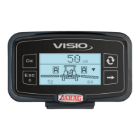
SETTING
- Access the selected menu
- Confirm changes and go back to previous menu
- Go back to previous menu
- Quit without confirming the changes
Pressed in sequence:
- Scroll the pages of a menu
- Change a value (increase)
Move the cursor during a change (press a
few times)
PROGRAMMING KEYSPROGRAMMING KEYS
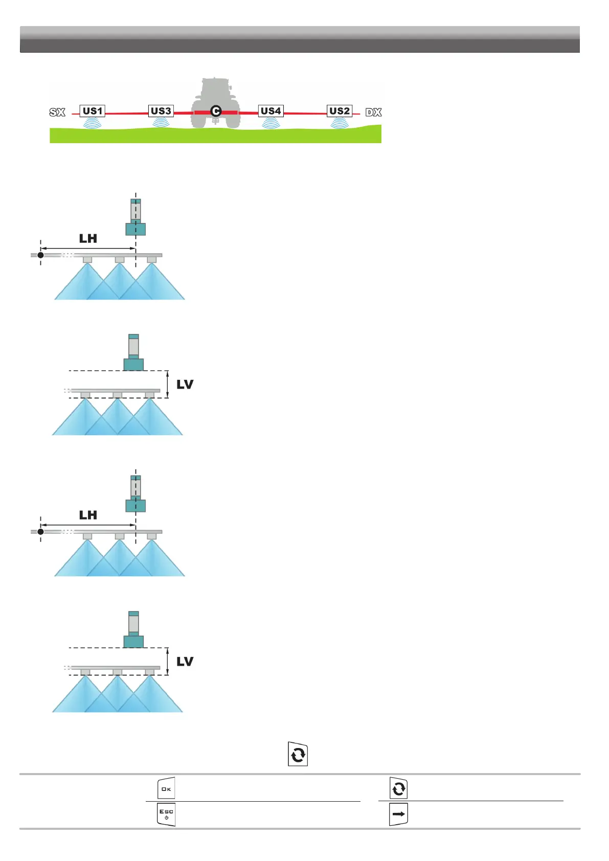
SYSTEM WITH 4 SENSORS
Fig. 30
• Number of sensors: 4 (US1 + US2 and US3 + US4). Number of ultrasonic sensors used by the BLC control.
• External sens. [X]: value relating to US1 + US2 (pair of external sensors).
BOOM BOOM
CENTERCENTER
ULTRASONIC ULTRASONIC
SENSORSENSOR
Fig. 31
Horizontal distance LH1 between the longitudinal axis of EXTERNAL sensors and boom center (Fig. 31).
Enter the value in the corresponding menu only once:
it is identical for the same pair of sensors.
• External sens. [Y]: value relating to US1 + US2 (pair of external sensors).
SENSOR SENSITIVE SENSOR SENSITIVE
SURFACESURFACE
NOZZLE OUTLETNOZZLE OUTLET
Fig. 32
Vertical distance LV1 between the sensitive surface of EXTERNAL sensors and nozzle outlet (Fig. 32).
The sensitive surface must be positioned ALWAYS HIGHER than the outlet (LV > 0 mm).
Enter the value in the corresponding menu only once:
it is identical for the same pair of sensors.
• Internal sens. [X]: value relating to US3 + US4 (pair of internal sensors).
BOOM BOOM
CENTERCENTER
ULTRASONIC ULTRASONIC
SENSORSENSOR
Fig. 33
Horizontal distance LH2 between the longitudinal axis of INTERNAL sensors and boom center (Fig. 33).
Enter the value in the corresponding menu only once:
it is identical for the same pair of sensors.
• Internal sens. [Y]: value relating to US3 + US4 (pair of internal sensors).
SENSOR SENSITIVE SENSOR SENSITIVE
SURFACESURFACE
NOZZLE OUTLETNOZZLE OUTLET
Fig. 34
Vertical distance LV2 between the sensitive surface of INTERNAL sensors and nozzle outlet (Fig. 34). The
sensitive surface must be positioned ALWAYS HIGHER than the outlet (LV > 0 mm).
Enter the value in the corresponding menu only once:
it is identical for the same pair of sensors.
• HL Button: select the device that will give the headland control HL.
External (external switch) or Keyboard (Visio keyboard, key ).