5
INSTALLATION
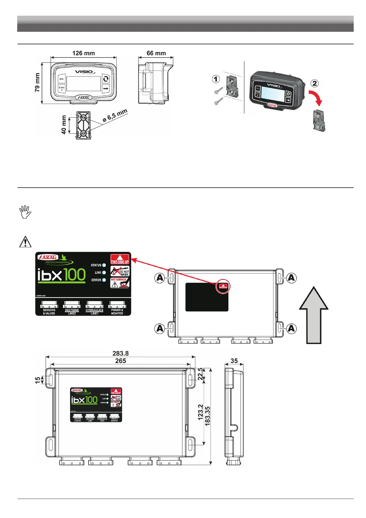
Fig. 3 Fig. 4
1 Set mounting rail in cabin and fasten it with the relevant screws (Fig. 4), in a position where VISIO can be easily seen and at hands' reach, but
away from any moving organs.
2 Secure VISIO to rail and push down until locked in place.
3 Fasten harnesses so that they do not interfere with any moving parts.
6.2 VISIO BLC
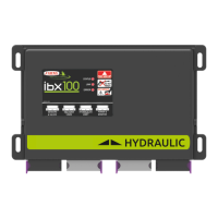
6.3 IBX100 hydraulic control unit fixing
Secure the control unit on the back of the machine, close to the hydraulic unit.
Consider all necessary connections of the device (par. 6.1), the cable length, and make sure there is enough space for
connectors and cables. For any reference to the system configuration read par. 6.1.
Respect the mounting direction of the control units, as specified in Fig. 5 (connectors shall be facing down).
Fix the IBX100 using the 4 bolts fitted into their slots (A, Fig. 5).
No other type of assembly is allowed.
Fig. 5
Fig. 6