7
INSTALLATION
7.1 Sensor correct identification and positioning
Two types of layouts are available:
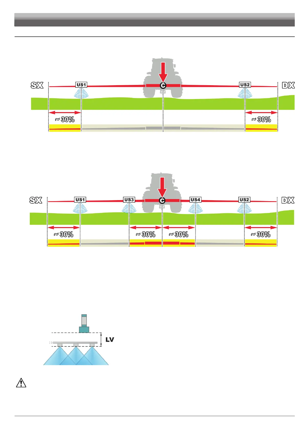
• BASIC SETUP - with a pair of sensors US1 + US2 (Fig. 9).
Fig. 9
Place the sensors in relation to the boom center CC:
US1 (LH side) + US2 (RH side) = external pair of sensors (far from boom center), at a distance from boom end corresponding
approximately to 30% of the half-boom length.
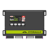
• COMPLETE SETUP - with two pairs of sensors US1 + US2 and US3 + US4 (Fig. 10).
Fig. 10
Place the sensors in relation to the boom center CC:
US1 (LH side) + US2 (RH side) = external pair of sensors (far from boom center) refer to basic setup.
US3 + US4 = internal pair of sensors (the ones closest to boom center), at a distance from boom center corresponding to
approximately 30% of the half-boom length.
Install the US1 / US3 sensors on the LH side of the boom and the US2 / US4 sensors on the RH side (rear view of the tractor).
The configuration with two pairs of sensors is to be preferred: in case of very large booms, it allows creating an average of the
distances of sensors from ground unevennesses.
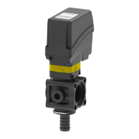
Furthermore, the sensitive surface of the sensors must be positioned ALWAYS HIGHER than nozzle outlet (LV > 0 mm,
Fig. 11).
SENSOR SENSITIVE SENSOR SENSITIVE
SURFACESURFACE
NOZZLE OUTLETNOZZLE OUTLET
Fig. 11
CHECK THAT SENSORS ARE CONNECTED TO THE CORRESPONDING CONNECTORS AS PER THE MARKING INDICATED IN
PAR. 8.3 WIRING HARNESS CONNECTION.
THE SYSTEM COULD NOT BE ACKNOWLEDGED OR BE ABLE TO OPERATE WITH DIFFERENT CONNECTIONS.