22
SETTING
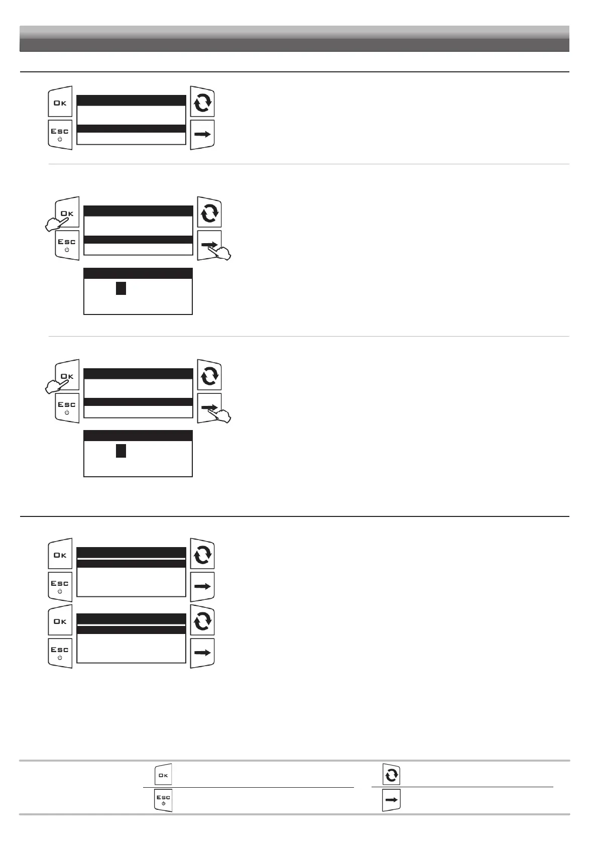
- Access the selected menu
- Confirm changes and go back to previous menu
- Go back to previous menu
- Quit without confirming the changes
Pressed in sequence:
- Scroll the pages of a menu
- Change a value (increase)
Move the cursor during a change (press a
few times)
PROGRAMMING KEYSPROGRAMMING KEYS
12.2.6 User access
Fig. 50
User access
Operator
Manager
Technician
ARAGTech
Access the Options > User access menu.
Set the user access level to the control parameters.
The preset access mode is
Technician.
Operator: user access level and minimum parameter number (simplified menu structure).
Manager: manager access level and limited parameter number (simplified menu structure).
Technician: maximum access level; access to all control parameters.
ARAGTech: for ARAG staff only (assistance). It requires an access PIN number.
ENTERING THE PIN NUMBER
ONLY Manager and Technician users can set an access PIN number, as follows:
Fig. 51
User access
Operator
Manager
Technician
ARAGTech
1
2
1
Select the access mode to enter the PIN number.
Example: select Technician to enter the Technician level PIN number.
2 Hold the key
pressed to display the PIN number entry page.
Fig. 52
Enter new PIN
12345
Min value 0
Max value 99999
Use of the keys at the bottom of the page.
3 Enter the PIN number and press OK. Confirm PIN: enter it again and confirm.
4 Restart the device.
Upon switching on, the system starts operating with the first user level without PIN number.
Example: if a PIN number for the Technician level has been set, the system starts operating
as Manager.
CANCELING THE PIN NUMBER
Fig. 53
User access
Operator
Manager
Technician
ARAGTech
1
2
1
Select the access mode. Enter the PIN number.
2 Hold key
pressed.
Fig. 54
Enter new PIN
00000
Min value 0
Max value 99999
Use of the keys at the bottom of the page.
3 Enter PIN 00000 and press OK. Confirm PIN: enter it again and confirm.
Now the level is unlocked and can be viewed by everybody.
12.2.7 Operating mode
Fig. 55
Operating mode
Only BLC
Only TTC
BLC and TTC
Access the Options > Operating mode menu.
Set the operating mode:
Only BLC
Fig. 56
Boom geometry
Fixed
Golf sprayer
Multi-row sprayer
By selecting the “Only BLC” option, you are then asked to select the type of geometry.
In the
Boom geometry menu, select the Fixed item