8
INSTALLATION
7.2 Sensor optimal orientation
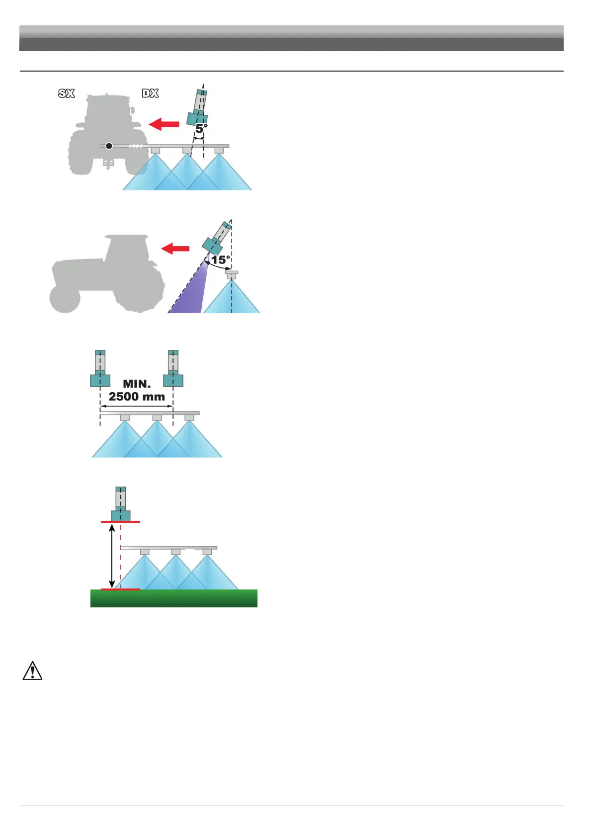
Fig. 12
• Lateral inclination (internal)
The sensors must be oriented towards the nearest side of the tractor; an inclination
of 5° is recommended and useful to compensate the gradient of the boom due to
the BLC system correction.
Fig. 13
• Forward inclination / height
As the ultrasound emission of the sensor has a conical shape with an amplitude of
approx. 15°, advance the sensors by 15° with respect to the tractor travel direction.
This inclination allows avoiding interferences with the cone outlet of the liquid
sprayed by the nozzles.
To optimize the sensor measuring capacity it might be also useful to move the
sensor position forward (always in relation to the travel direction) and / or increase
their height with respect to the nozzle outlet.
ALWAYS avoid the range of action of the sensor to superimpose the
spraying cone.
Fig. 14
• Minimum distance between the sensors
If the sensors are too close to one another ultrasound superimpositions may occur
causing system errors: respect the minimum distance of 2500 mm.
MIN.
25O mm
Fig. 15
• Minimum distance between the sensor and the ground
Position the sensor at a height such as to have a minimum distance of 250 mm
from the ground, in all possible working conditions.
A distance smaller than this threshold does not allow the correct operation of
the sensor, causing a wrong height measurement and possible unforeseen
movements.
It is the installer responsibility to check that the measurements detected by the sensors are correct and to avoid possible
interferences with the cone outlet of the liquid sprayed by the nozzles.