CYC5000 User Guide www.arrow.com
Page | 48 March 2023
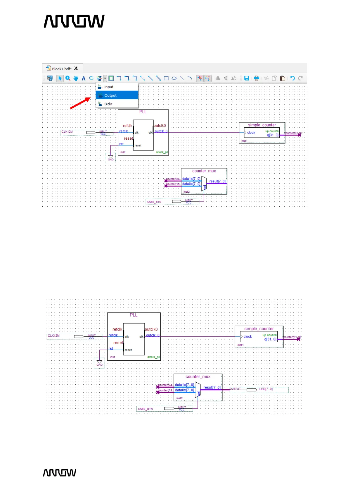
5.2.9.6 Click on the “Pin Tool” as before, but this time select “Output”.
5.2.9.7 Add one output pin for the LEDs.
5.2.9.8 Rename the pin to LED[7..0].
5.2.9.9 Using the “Bus Tool”, make the connection between counter_mux component and
output pin:
result[7..0] → LED[7..0]
The final schematic should look like the following:
Looking at the schematic, even though the buses are not connected together by wires,
the names of counter tell Quartus Prime to connect the signals together. Overall, the
user button will toggle between displaying higher 8 bits of the counter and 8 lower bits