3 of 3
P/N PM000152A • Rev. 1.0 • ISS 09MAY2017
3. Press the room display firmly against the backplate so that
the Room Display’s top fasteners snap closed on the
backplate.
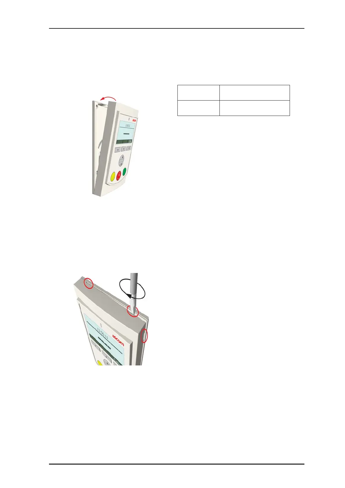
Removal
Follow the steps below to remove the NURD Room Display
from the backplate.
Note: Failure to follow the proper removal procedure may
result in damage to the room display.
1. Insert a 6mm flat-blade screwdriver into one of the
indentations at the top or side of the NURD module.
2. Gently twist the screwdriver to disengage the Room
Display from the backplate. Do not use excessive force
while twisting.
3. Remove the Room Display from the backplate.
Specifications
Wire/terminations
Cat5/5e/6/7 U/UTP
NOTE: Cat 6/7 cable will work electrically
but may be too stiff for some backboxes.
Compatible electrical
boxes
European Union, United Kingdom:
Standard plastic or metal back box with
mounting holes: 60mm (2.36in.).