2 of 3
P/N PM000204A • Rev. 1.00 • ISS 23MAY2017
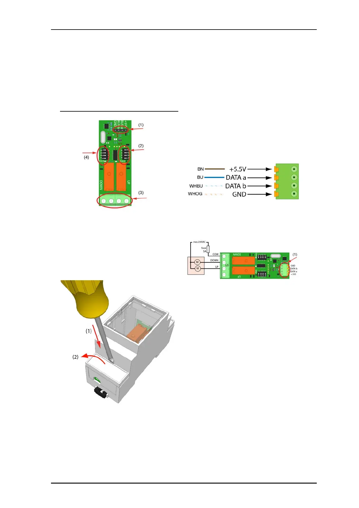
The following figure shows the DIP switches and cable
connections on the NUSB2-H module.
NUSB2-H module connections
Legend
(1) 4x 4-pole I/O connection to room bus
(2) DIP switches for bus addressing (not in use)
(3) Screw terminals for motor control
(4) DIP switches for bus addressing (not in use)
To connect a NUSB2-H Sun Blind Control module:
1. Remove the connector cover by inserting a number 2 flat
blade into the notch at the top of the connector cover and
applying light downward pressure.
2. The module uses a 4-pole terminal block to connect the
module to the room bus’s eight wire cable (Cat 5/5e/6/
7). If this is the last module on the bus, the four unused
wires should be folded back and taped to the room bus
cable. If this module is to be daisy-chained to another
module down-line on the bus, you must terminate the 4-
pole block connector with matching wires from the eight
wire room bus cable that goes to the next module. You
must terminate the unused wires on a separate 4-pole
block connector, or similar connector, with the matching
wires from the next room bus.
3. Attach the 4-pole block connector module to the 4-pole
I/O connection. Ensure the connector is seated properly
on the terminal pins (Number 1 in the figure below).
4. Connect the DOWN and UP wiring for the sun blind motor
to the appropriate screw terminals as shown.
Legend
(1) 4-pole block connector to room bus
(2) Screw terminals for motor control
Note: The 230VAC maximum power to the sunblind motor
control relay must be fused at 5 Amps. Appropriate
cable for the voltage and current must be used for
the sun blind motor control.
5. Complete the electrical circuit for the sun blind motor by
connecting the COM from the sun blind motor to the
COM screw terminal.
Warning: Sun blind motors are wired to the facility’s main
power grid and are high voltage devices. Improper
installation or handling of electrical wires can result
in severe injury or death. Installation should be
conducted only by licensed individuals.