4 of 5
P/N PM000117A • Rev. 2 • ISS 09MAY2017
Terminating EoL with 22kΩ Resistors for 24VDC system
To connect a NUCL4P-H light module:
1. Attach the primary 8-pole room bus connector cable to the
8-pin primary terminal. See figure “NUCL4P-H connectors
and jumper”, item 2. Ensure that the connector is seated
properly.
2. If connecting to another module on the room bus, attach
the 8-pole secondary room bus connector cable to the
8-pin secondary terminal. See figure “NUCL4P-H
connectors and jumper”, item 1.
3. If the fourth section of the light is to illuminate blue, set
the jumper on the two pins marked BLUE. If the fourth
section is to illuminate white, set the jumper on the pins
marked White. See figure “NUCL4P-H connectors and
jumper”, item 3.
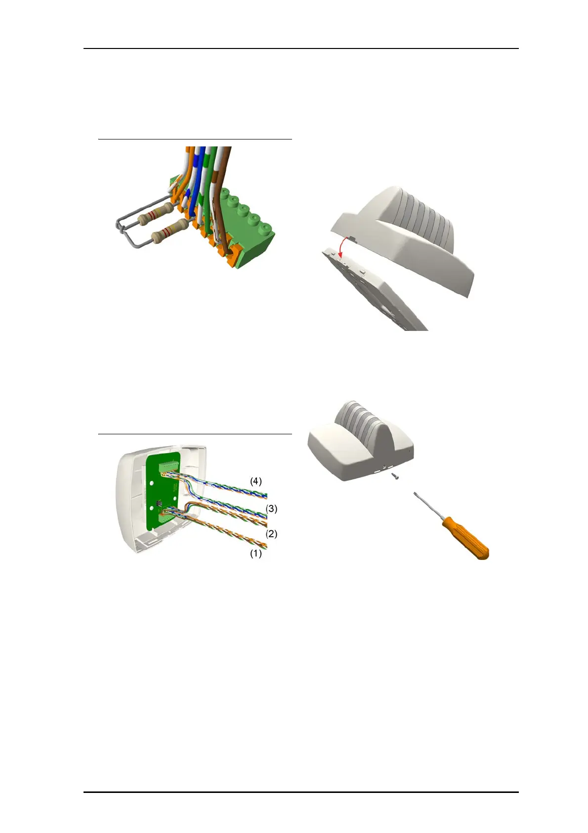
NUCL4P-H Room Bus Connections
Legend
(1) From the previous device on the primary bus
(2) To the next device on the primary bus
(3) From the previous device on the secondary bus
(4) To the next device on the secondary bus
To mount the light to the backplate:
1. Ensure that all cable connections are properly secured to
the jacks and terminals on the back of the light.
2. Place the light on to the two top fasteners on the
backplate.
3. Press the light firmly against the backplate so that the
light’s bottom fasteners snap closed on the backplate.
4. Insert the locking screw into the bottom of the light, and
then tighten the screw until it is snug, as shown below.
Do not over tighten.