2 of 3
P/N PM000119A • Rev. • ISS -812017
To make the connections to the module:
1. Pull the cables from the backbox or spacer, and then slide
them though the module’s frame.
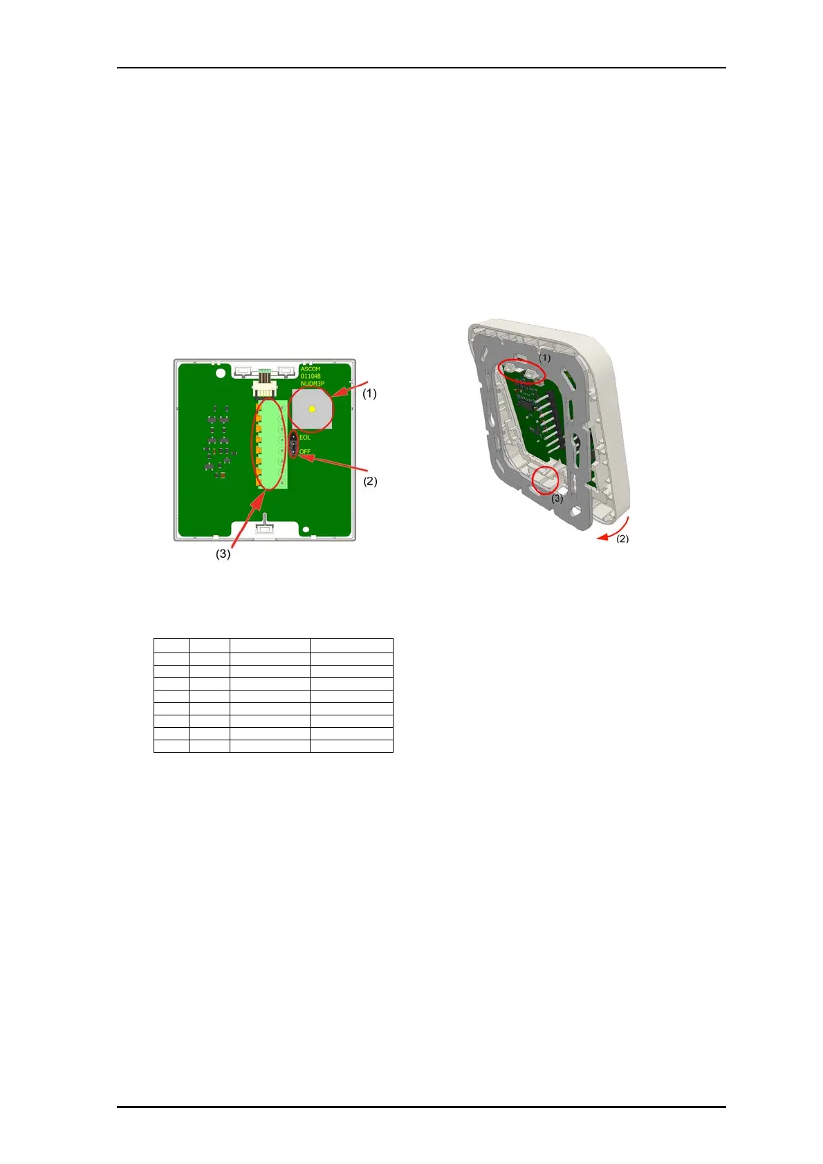
Passive Customizable Module Connections and Jumper
The module connects to a passive room bus using an 8-pole
connector. It can also be daisy-chained with other peripheral
devices on same bus. The connector carries 5.5VDC power,
input, and output lines.
The module includes a jumper to activate and End-of-Line
resistor (EOL) when the module is last module on the passive
bus.
Legend
(1) Buzzer
(2) Jumper for end-of-line (EOL)
(3) 8-pole connector for a passive room bus
8-pole Passive Bus Connection Pinouts
To connect a passive customizable button module:
1. Slide the cables with their connectors through a module
frame.
2. If this is the last device on the passive room bus, move the
EOL jumper to the pins labeled EOL; otherwise, leave the
jumper in its default position (OFF). See the previous
figure, item 2.
Note: EOL must also be configured in the system using the
System Configuration Tool.
Pin # Pin Description Color
1 +V Positive power Orange/White
2R Reset Orange
3L_RDLED Red Blue/White
4S Set Blue
5 C C-line Green/White
6 L_GR LED Green Green
7 L_YL LED Yellow Brown/White
8 GND Ground Brown
3. Attach the 8-pole room bus connector cable to the 8-pin
terminal. See item 3. Ensure the connector is seated
properly on the pins.
To attach the module on the adapter:
1. Place the module against the frame, ensuring that the
module is facing up.
2. Place the module’s upper snap fasteners against the
upper edge of the adapter (see item 1 in the following
figure).
.
3. Press the module firmly against the adapter so that the
module’s bottom fasteners (see item 3 in the previous
figure) snap closed on the adapter.