Copyright © 2016 ASIX Electronics Corporation. All rights reserved.
AX99100
PCIe to Multi I/O Controller
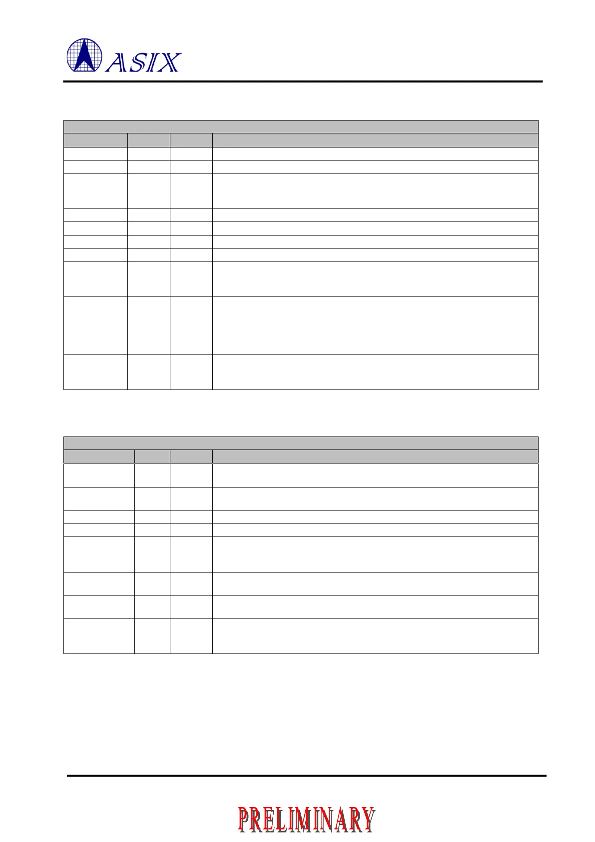
Table 1-2: PCIe Pin Description
PCIe PHY differential PLL reference clock.
PCIe PHY differential PLL reference clock.
Bandgap External Resistor
Connect this pin to ground through an external resistor of 20KΩ, ±1%. The total
parasitic capacitor of this pin to ground must be less than 10 pF
PCIe PHY differential negative serial data input.
PCIe PHY differential positive serial data input.
PCIe PHY differential positive serial data output.
PCIe PHY differential negative serial data output.
An open-drain, active low signal that is driven low by a PCI Express function to
reactivate the PCI Express Link hierarchy’s main power rails and reference
clocks.
Reference clock request signal
This pin is an open drain, active low signal that is driven low by the PCI Express
Mini Card function to request that the PCI Express reference clock be available
(active clock state) in order to allow the PCI Express interface to send/receive
data.
Active low asynchronous reset from PCIe.
Indicates when the applied main power is within the specified tolerance and
stable.
Table 1-3: Power/Ground Pin Description
Digital Power for I/O pins, 3.3V
Please add a 0.1uF bypass capacitor between each VCCIO and GND.
Digital Power for core, 1.2V
Please add a 0.1uF bypass capacitor between each VCCK and GND.
Ground for all Analog and Digital Power.
Analog Power for Regulator, 3.3V
1.2V Power Output of on-chip 3.3V to 1.2V Regulator.
The regulator requires an external capacitor (at least 3.3 μF) with low ESR for
frequency compensation and stability maintenance.
Analog Power for PCIe Transmitter, 1.2V.
Please add a 0.1 and 10 uF bypass capacitor between VCC12A_TX and GND.
Analog Power for PCIe Transceiver, 1.2V.
Please add a 0.1 and 10 uF bypass capacitor between VCC12A_D and GND.
Analog Power for PCIe Auxiliary, 1.2V.
Please add a 0.1 and 10 uF bypass capacitor between VCC12A_AUX and
GND.
 Loading...
