Copyright © 2016 ASIX Electronics Corporation. All rights reserved.
AX99100
PCIe to Multi I/O Controller
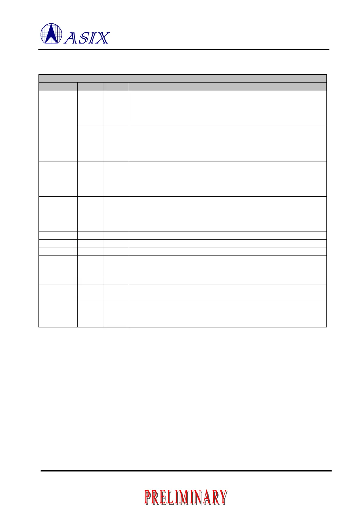
1.4.6 Parallel Port
Table 1-9: Parallel Port Pin Description
SPP:
O5/T/4m
Others:
O5/4m
Set active low by the host to transfer data into the input latch of the peripheral.
Data are valid while STROBEn is low.
The pin is open-drain when operation in SPP mode, otherwise, is direct drive
logic 0 or logic 1.
SPP:
O5/T/4m
Others:
O5/4m
The interpretation of this signal varies from peripheral to peripheral. Set low by
host to put some printers into auto-line feed mode
The pin is open-drain when operation in SPP mode, otherwise, is direct drive
logic 0 or logic 1.
SPP:
O5/T/4m
Others:
O5/4m
Pulsed low by the host in conjunction with IEEE 1284 Active low to reset the
interface and force a return to Compatibility Mode idle phase
The pin is open-drain when operation in SPP mode, otherwise, is direct drive
logic 0 or logic 1.
SPP:
O5/T/4m
Others:
O5/4m
Set low by host to select peripheral
The pin is open-drain when operation in SPP mode, otherwise, is direct drive
logic 0 or logic 1.
Parallel Port Data Transfer Direction Indications
Pulsed low by the peripheral to acknowledge transfer of a data byte from the host
Driven high by the peripheral to indicate that it is not ready to receive data
Driven high by the peripheral to indicate that is has encountered an error in its
paper path. The meaning of this signal varies from peripheral to peripheral.
Peripherals shall set FAULTn low whenever PAPEREND is set high
Set high to indicate that the peripheral is online
Set low by the peripheral to indicate that an error has occurred. The meaning of
this signal varies from peripheral to peripheral
43, 44,
45, 46,
47, 48,
49, 50
Driven by the host in Compatibility Mode and the negotiation phase, not used in
Nibble Mode, and bidirectional in all other modes
Note: Above signals are only valid when CHIP_MODE = 010 and 001.
 Loading...
