Copyright © 2016 ASIX Electronics Corporation. All rights reserved.
AX99100
PCIe to Multi I/O Controller
1.4.8 Local Bus Interface
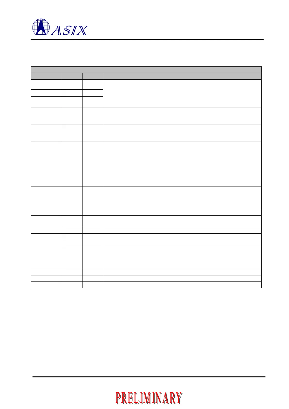
Table 1-11: Local Bus Pin Description
Local Bus Address Bus, A[2:0]
These pins are input direction during chip reset use to bootstrap the mode setting
to decide the operation mode. Please reference to Section 3.1.
In Local Bus mode, These pins should always use external pull-down resistors to
ground.
Local Bus Address Bus, A[3]
This pin should be connected to the 3.3V AUX in PCIe slot via an external
pull-up resistor. It is used to detect the 3.3V AUX is existed or not.
Local Bus Address Bus, A[9:4]
The A[9:0] are outputs and provide up to 10 Local Bus address lines in
non-multiplexed address and data bus format
61, 62,
63, 64,
65, 66,
67, 68,
1, 2,
4, 3,
5, 7,
8, 9
Data and Address bus
Multiplexed mode: address on bus when ALE issued, other time data on bus
Non-multiplexed mode: data always on bus
Local Bus Reset Output
The output polarity can be decided by adding external pull up/down resistor. If
connected this pin to VCCIO via external pull-up resistor, means RSTO is active
high. If pull-down to ground, means active low.
Local Bus Chip Select 1
Local Bus Chip Select 0
Address Latch Enable
When in non-multiplexed mode, ALE can choice remap to A[10] (detail
description same as above A[9:0]) or address latch enable for ISA bus type
When in multiplexed mode, ALE for address latch enable
Note: Above signals are only valid when CHIP_MODE = 000.
 Loading...
