Copyright © 2016 ASIX Electronics Corporation. All rights reserved.
AX99100
PCIe to Multi I/O Controller
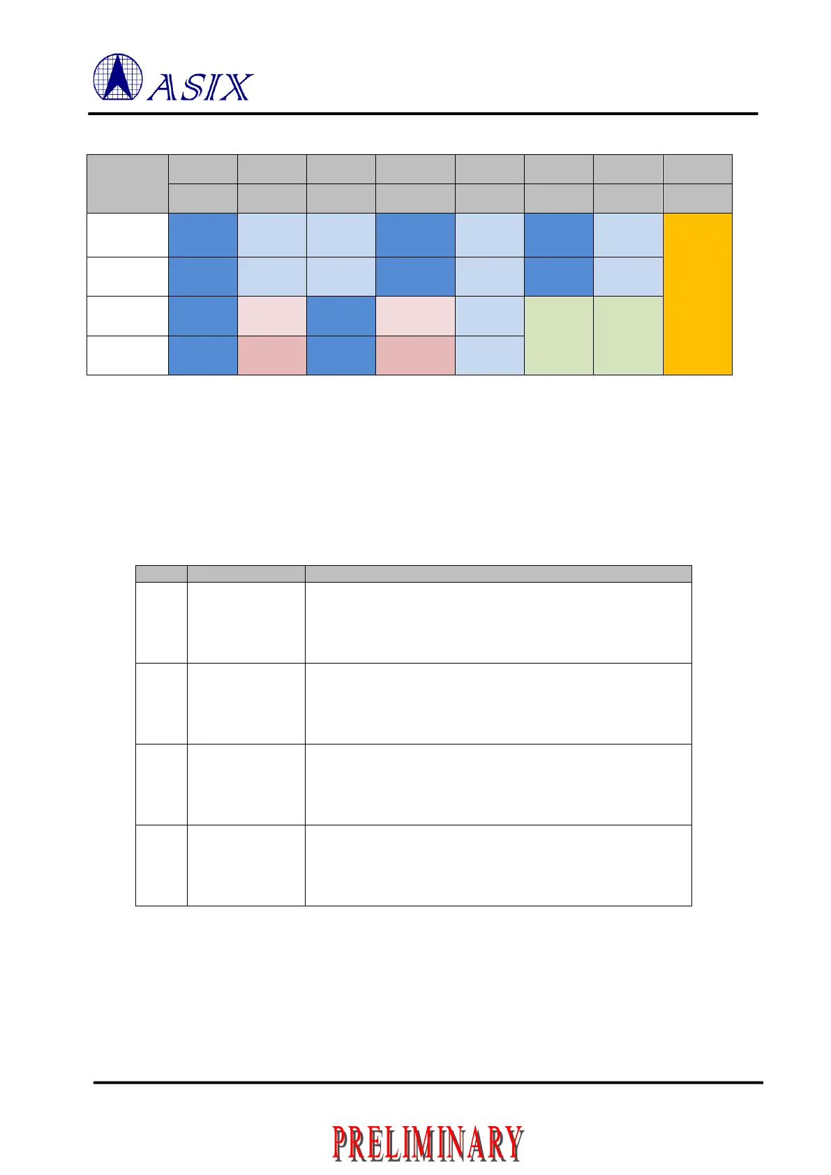
Table 3-2: Chip Mode Selection Table
Note: The AX99100 Multi-protocol Mode is designed to support the Multi-protocol transceiver. Please contact ASIX
product support for the detail.
DTR Boot Strapping Pins for Serial Port 3.2
Each Serial Port or Serial Port with multi-protocol transceivers mode can support for RS-232 or RS-485 function, the
DTR/DXEN pin will has different behavior for the both mode. In Hardware design, each DTR/DXEN pin has internal
pull-down during reset. User may use the external pull-up resister to decide which mode is selected for operation.
DTR Mode Select bit 0 for Serial Port 1
1: Added external pull-up resistor to this pin. It works for RS-232
mode with active low.
0: Otherwise, means to use internal pull-down to this pin. It works
for RS-485 mode with active high.
DTR Mode Select bit 1 for Serial Port 2
1: Added external pull-up resistor to this pin. It works for RS-232
mode with active low.
0: Otherwise, means to use internal pull-down to this pin. It works
for RS-485 mode with active high.
DTR Mode Select bit 2 for Serial Port 3
1: Added external pull-up resistor to this pin. It works for RS-232
mode with active low.
0: Otherwise, means to use internal pull-down to this pin. It works
for RS-485 mode with active high.
DTR Mode Select bit 3 for Serial Port 4
1: Added external pull-up resistor to this pin. It works for RS-232
mode with active low.
0: Otherwise, means to use internal pull-down to this pin. It works
for RS-485 mode with active high.
Table 3-3: DTR Mode selection Pins
 Loading...
