26
EN
Notes
Intended use
The Technilock
®
L4 is used for door locking in high security areas. The device is suitable for installation in
the frame and in the door leaf according to the installation instructions. It is not intended for any other
type of use.
Explanation of terms
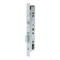
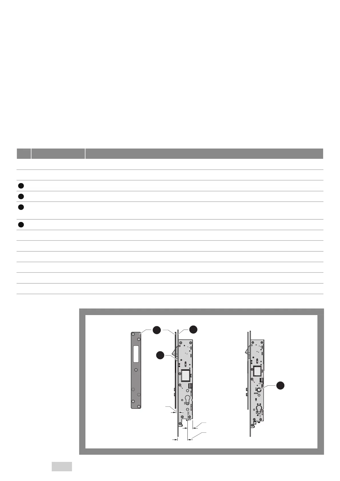
Fig. 2:
Explanation of terms
Version with follower
4
2
1
3
A
B
C
– Fail-unlocked The “fail-unlocked” product variant locks if electrical current flows (Fig. 1, page 24).
– Fail-locked The “fail-locked” product variant locks if no electrical current flows (Fig. 1, page 24).
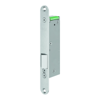
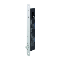
1 Striking plate The striking plate is the counterpart to the lock installed in the door frame.
2 Face plate The face plate is screwed onto the door and fixes the Technilock
®
L4 in the lock pocket.
3 Control latch The control latch extends to the striking plate when the door is closed, and is pushed inward in the
process.
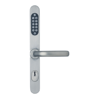
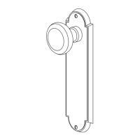
4 Follower / handle pin The handle pin is a square pin which is guided through the follower and ends in the door handle.
A Rebate gap The rebate gap is the distance between the face plate and striking plate.
B Backset behind The backset behind is the distance from the centre of the keyhole to the rear edge.
C Backset The backset is the distance from the centre of the keyhole to the front edge.
– Profile cylinder The profile cylinder (locking cylinder) is installed and screwed into the opening of the door bolt box.
– Cylinder unlocking Cylinder unlocking takes place when the Technilock
®
L4 is unlocked via the locking cylinder.
– Lock pocket The lock pocket is the recess in the door or in the door frame to accommodate the Technilock
®
L4.
 Loading...