32
EN
Fitting and installation
Installation
Warning!
Life-threatening danger due to electric shock: Incorrect wiring is life-threatening and can ruin the Techni-
lock
®
L4. The connection of the supply current may only be performed by trained qualified personnel.
Caution!
Risk of injury due to sharp edges and chips: Drilling and other cutting work entails the risk of injury due
to sharp edges and chips. Be especially sure to protect your eyes with suitable safety goggles. Assign an
appropriately trained, qualified person with the work.
Preparation for installation
1 Create the lock pocket in a suitable mounting position corresponding to Fig. 5.
2 Create the holes for the fixing screws corresponding to Fig. 5.
3 Create the holes for the lock fittings.
4 Clean the lock pocket and all created holes by blowing them out or using a vacuum cleaner.
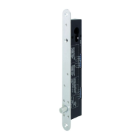
Electrical connections
1 Prepare the wiring for the Technilock
®
L4 corresponding to the chapters “Electrical connection”, page
34 and “Power supply”, page 35.
2 Connect the cables for the supply current and control, corresponding to the chapters “Electrical
connection”, page 34 and “Power supply”, page 35.
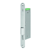
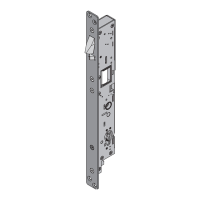
Mounting the Technilock
®
L4
1 Screw the Technilock
®
L4 in place in the lock pocket (Fig. 5).
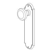
2 Fix the lock fittings.
3 Check the Technilock
®
L4 for ease of movement.
The Technilock
®
L4 is ready for operation once the striking plate is mounted.
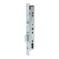
Mounting the striking plate
1 Create the striking plate pocket and all holes (Fig. 4 –
1 ).
2 Clean the striking plate pocket and all drilled holes by blowing them out or using a vacuum cleaner.
3 Screw on the striking plate, which matches the Technilock
®
L4 to be installed.
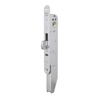
4 Check the Technilock
®
L4 for ease of movement. The rebate gap must be between 3,5 mm and 5,5 mm.
With an adjustable striking plate (Fig. 5), position the filler plate so that the bolt of the Technilock
®
L4
engages optimally in the striking plate pocket.
The Technilock
®
L4 is ready for operation.
Checking the Technilock
®
L4
1 Test all functions of the Technilock
®
L4.
2 Mount the fittings.
The Technilock
®
L4 is completely mounted and has been checked for functionality.
!
!
Prepare and clean the
lock pocket
Connect the cable
Screwing in the
Technilock
®
L4
Screw in the striking
plate matching
the Technilock
®
L4
Check the Technilock
®
L4
for full functionality
 Loading...