34
EN
Fitting and installation
Electrical connection
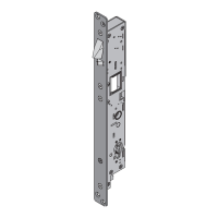
Terminal assignment
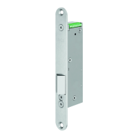
The Technilock
®
L4 board with connecting terminals is compatible with the Technilock
®
L3 series.
1: GND / mass Note: Mass potential: Pin 1 and 3 must be equal.
2: 24 V DC
3: Activation Note: Mass potential: Pin 1 and 3 must be equal.
4: Bolt contact (non-isolated, electrical load capability: max. 25 mA)
5: Door status (non-isolated, electrical load capability: max. 25 mA)
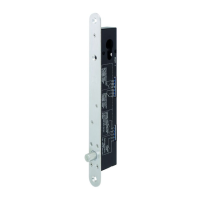
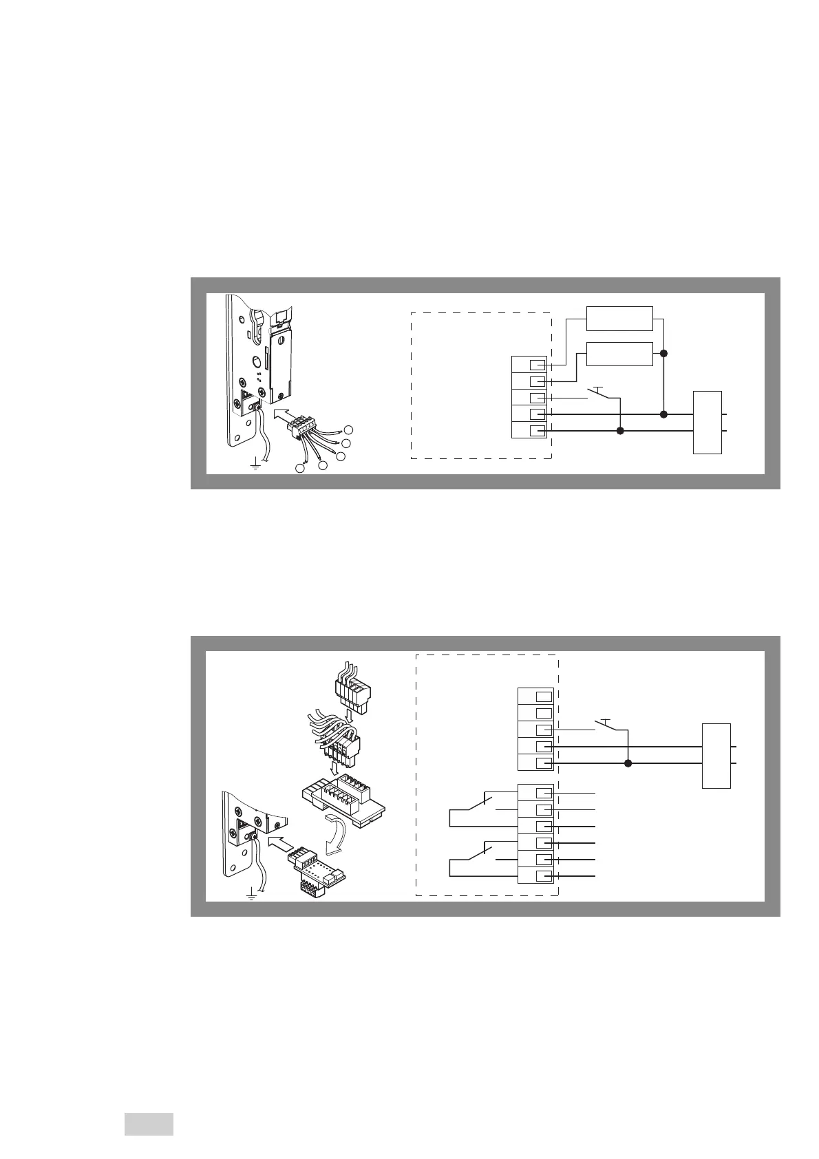
Connection assignment of the adapter board
The optionally available adapter board with potential-free contacts is compatible with the Technilock
®
L4
series without follower.
Electrical load capability of the contacts 30 V / 0.5 A
Terminal strip S1
1: GND / mass
2: 24 V DC
3: Activation
4: free
5: free
Terminal strip S2
1: Bolt signal (IN) (Common)
2: Bolt locked (OUT) (NO)
3: Bolt unlocked (OUT) (NC)
4: Door signal (IN) (Common)
5: Door closed (OUT) (NO)
6: Door open (OUT) (NC)
The connection diagram shows the
assignment of the output signals in the
standard configuration. Other monito-
ring signals are also adjustable with the
rotary switch (“Settings on the rotary
switch”, page 29).
Fig. 6 :
Electrical connection
without supplementary
board
54321
24V DC
main adapter
230V AC
50Hz
4
5
3
2
1
Consumer load
max. 25 mA
Consumer load
max. 25 mA
−
+
Electronic circuit board
compatible with
Technilock
®
L3
5432154321
24V DC
main adapter
230V AC
50Hz
1
3
2
1
3
2
4
5
6
6
−
+
Only for Technilock
®
L4
without follower
Fig. 7 :
Electrical connection
with supplementary
board
Adapter board
of the Technilock
®
L4
 Loading...