29
Functions and operation
EN
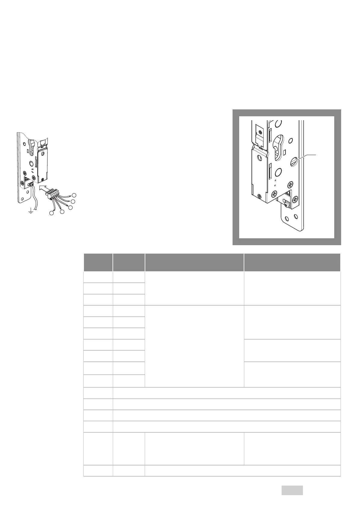
Settings on the rotary switch
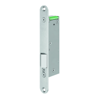
The rotary switch (Fig. 3 Pos. 1) can be used to adjust the
following settings:
· the unlocking duration and
· the meaning of the status signals through the two out-
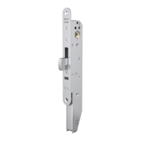
puts (Fig. 6):
· Output 4 reacts to the bolt position and
· Output 5 reacts to the door position.
With the use of the adapter board, the non-isolated
outputs are switched to potential-free outputs. The
terminal assignment for output 4 / 5 without adapter plate
is shown in Tab. 1. The conversion to potential-free
outputs is described in the chapter “Connection assign-
ment of the adapter board”, page 34 .
Output 4 is set to low in idle mode.
Output 5 is set to high in idle mode, so that an alarm or
tampering signal can be issued during a power failure, if
the corresponding rotary switch position was set.
Switch
position
Unlocking
duration
Output 4
(Status signal 4)
Output 5
(Status signal 5)
0 (default) 0.5 s
Locked low
Unlocked high
Door closed low
Door open high
1 2.0 s
2 4.0 s
3 0.5 s
Locked and door closed low
Locked and door open high
Unlocked and door closed high
Unlocked and door open high
No signal high
Alarm or tampering low
4 2.0 s
5 4.0 s
6 0.5 s
No signal high
Unlocking via cylinder low
7 2.0 s
8 0.5 s
No signal high
Alarm, tampering or
unlocking via cylinder low
9 2.0 s
A not defined
B not defined
C not defined
D not defined
E 0.5 s
Locked and door closed low
Locked and door open high
Unlocked and door closed high
Unlocked and door open high
Only with OEM version U4:
No signal high
Alarm or tampering low
F – May not be adjusted
1
Fig. 3 :
Rotary switch
4
5
3
2
1
Tab. 1 :
Meaning of rotary switch
positions
 Loading...