30
10. SCANNER OUTPUTS : Optional scanner matrix that provides 8 HV/Return
connections and 8 Ground Bond connections. Please refer to the Options section
of this manual for additional connection information
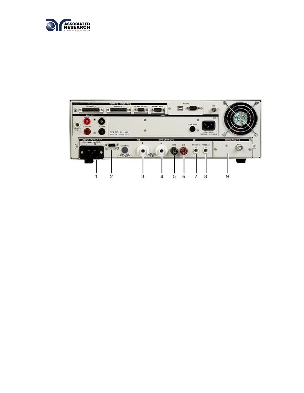
3.2.3. Additional Rear Panel Controls Models 82x6 and 82x7
1. DUT POWER INPUT CONNECTOR: This connector provides the Line and Neutral
input power connections on pin 1 and 2 respectively. An external single phase
unbalanced AC power supply with a single Hot or Line conductor should be
connected here to supply power to the DUT while performing the leakage test. This
input is rated for 0-277 volts 50/60 Hz.
2. REMOTE OUTPUT: Optional connector used to interface the OMNIA with an APT
AC power source for remote memory selection (Option 05).
3. L OUTPUT TERMINAL: Connector used to attach the adapter box high voltage
test lead to the instrument. Line power is supplied to the DUT during the run test or
Leakage Current test through this connector and High Voltage is supplied to the
DUT through this connector during the Dielectric Withstand or Insulation
Resistance tests. This terminal and the “N” terminal are shorted together when the
Dielectric Withstand or Insulation Resistance tests are being performed.
4. N OUTPUT TERMINAL: Connector used to attach the adapter box return test
lead to the instrument. Line power is supplied to the DUT during the run test or
Leakage Current test through this terminal and High Voltage is supplied to the
DUT through this terminal during the Dielectric Withstand or Insulation Resistance
tests. This terminal and the “L” terminal are shorted together when the Dielectric
Withstand or Insulation Resistance tests are being performed.
5. CASE: Connector used to attach the return lead to the DUT case or dead metal.
Provides the return for the Ground Bond, Dielectric Withstand, and Insulation
 Loading...