29
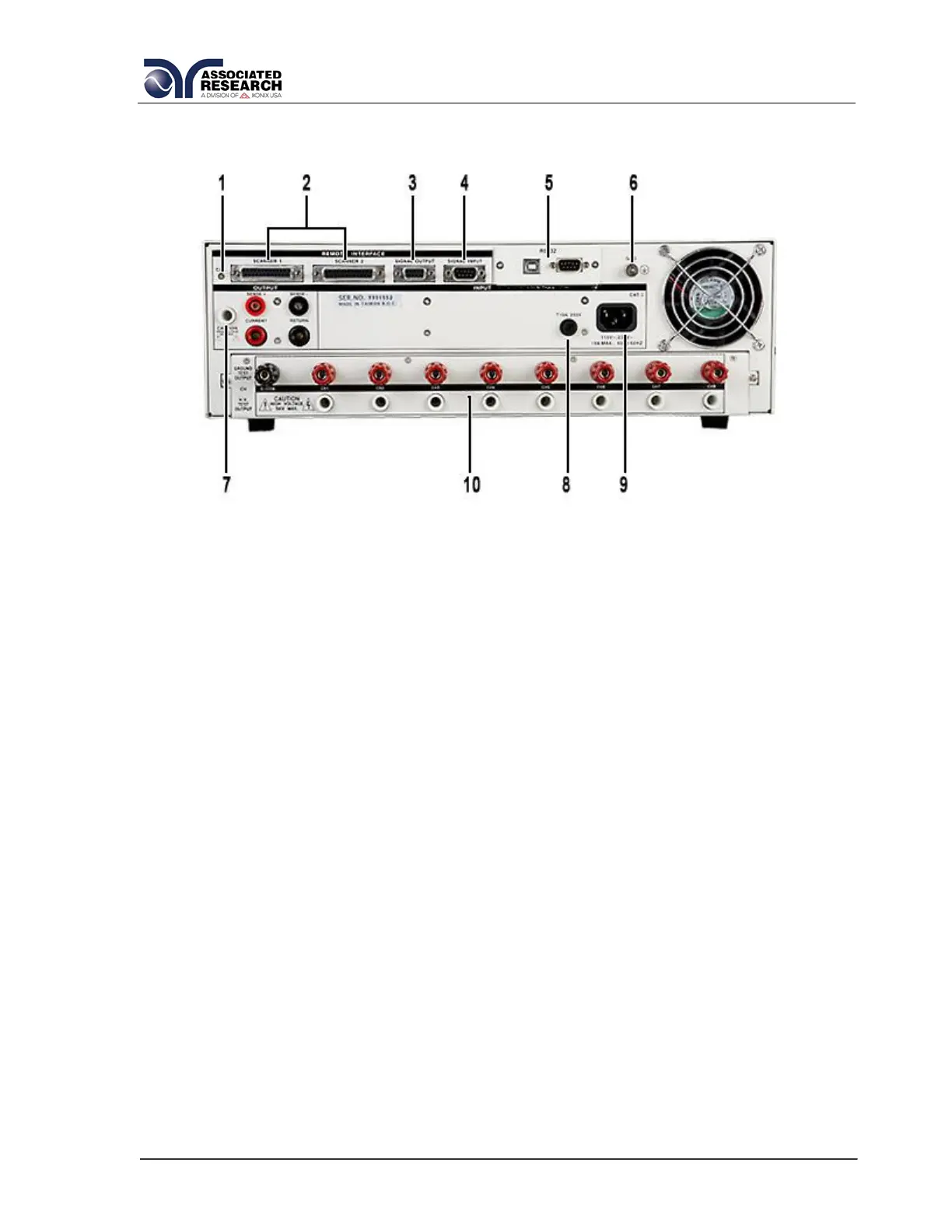
3.2.2. Rear Panel Controls
1. CALIBRATION BUTTON: To put the instrument into the calibration mode push
this button and turn on the power switch simultaneously.
2. SCANNER CONNECTOR: For connection of optional external Scanner.
3. REMOTE SIGNAL OUTPUT: 9-Pin D sub-miniature female connector for
monitoring PASS, FAIL, and PROCESSING output relay signals (See section 6.0.
Connection of Remote I/O for more detailed information).
4. REMOTE SIGNAL INPUT: 9-Pin D subminiature male connector for remote
control of TEST, RESET, and REMOTE INTERLOCK DISABLE functions, as well
as MEMORY SELECTION (See section 6.0. Connection of Remote I/O for more
detailed information).
5. BUS INTERFACE: Standard connector for interconnection to the USB/RS-232
Bus interface. Optional IEEE 488 or Ethernet may be substituted for USB/RS-232.
6. CHASSIS GROUND (EARTH) CONNECTION: This terminal should be connected
to a good earth ground before operation.
7. REAR PANEL OUTPUT TERMINALS: 2
nd
set of output connectors in parallel
with the front panel connectors.
8. FUSE RECEPTACLE: To change the fuse, unplug the power (mains) cord and
turn the fuse receptacle counter-clockwise. The fuse compartment will be exposed.
Please replace the fuse with one of the proper rating.
9. INPUT POWER RECEPTACLE: Standard IEC 320 connector for connection to a
standard NEMA style line power (mains) cord.
 Loading...