75
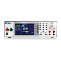
From the Continuity Parameter Setting screen, the following parameters may be
controlled: HI-Limit, LO- Limit, Dwell Time, Offset, Scanner Channel, Step Name and
Defaults.
Offset
This function allows the instrument to compensate for lead and test fixture resistance
during a Ground Bond or Continuity test. Using the up and down arrow keys or the
ENTER key, scroll the highlighted area to the Offset parameter. You may now
manually or automatically set an Offset value.
To manually set an Offset value enter a milliohm value via the numeric keypad and
then press the ENTER key to accept the new value or press the EXIT key to escape
from the edit.
To automatically set an Offset value set the output voltage, current, and frequency to
the values that will be used on the DUT and connect the test cables, test fixture, or
Scanner channel to the instrument. Next, short the ends of the test cables and press
the TEST button. The highlighted parameter field will briefly show the word
“READING” and then display the new value. The new value is automatically updated
in the field and does not allow an escape to the original value or require that the
ENTER key be used to accept the new parameter.
4.5.7. Functional Run Test (Models 82x6 and 82x7)
Associated Research recommends performing a Hipot test with the Fail Stop ON prior
to performing a Run Test or Leakage Current test. Performing a Hipot test first can
detect if a DUT is shorted line to ground before applying line power to it.
From the Setup Tests, Tests Selection screen, press the “Run Test” soft key. The
Run Test Parameter Setting screen will now be displayed. The Run Test Parameter
 Loading...