Manual, Robotic Tool Changer, QC-5 through QC-27
Document #9610-20-2254-09
Pinnacle Park • 1041 Goodworth Drive • Apex, NC 27539 USA • Tel: 919.772.0115 • Fax: 919.772.8259 • www.ati-ia.com
30
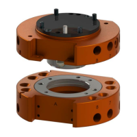
5. If the Tool Changer has a cover plate, remove the (2) M3 socket at head screws that secure the
cover plate to the Tool Changer Master plate using a 2 mm hex key.
6. Lift the cover plate off of the Tool Changer Master plate.
7. Make sure the O-ring in the Master plate is present and in good condition, lubricate with
Magnalube if needed.
Figure 3.14—QC-20 and QC-21 Cover Plate Removal
Cover Plate
O-ring
Tool Changer
Master Plate
M3 Socket Flat
Head Screws
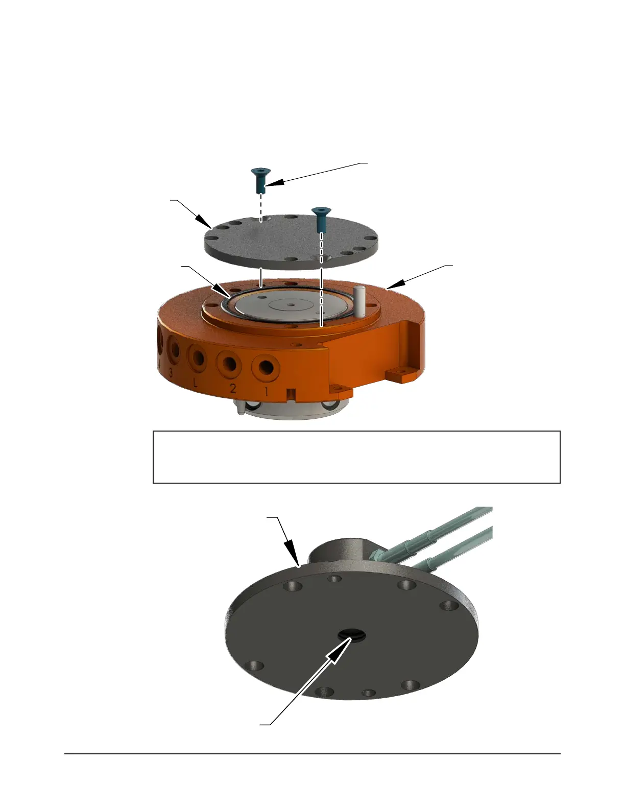
NOTICE: The sensor plate assembly comes assembled with the lock and unlock sensor
installed. Do not remove the sensors. The sensors have been positioned properly from
the factory. The sensor plate assembly has the detection shaft O-ring installed and
lubricated, make sure it is present as shown in Figure 3.15.
Figure 3.15—QC-20 and QC-21 Sensor Plate Assembly with Lock/Unlock Sensors and O-ring
O-ring
Sensor Plate
Assembly