111
ATtiny26(L)
1477G–AVR–03/05
Note: 1. [XA1, XA0] = 0b11 is “No Action, Idle”. As long as XTAL1 is not pulsed, the Com-
mand, Address, and Data Registers remain unchanged. Therefore, there are no
problems using BS2 as described below even though BS2 is multiplexed with XA1.
BS2 is only asserted when reading the fuses (OE
is low) and XTAL1 is not pulsed.
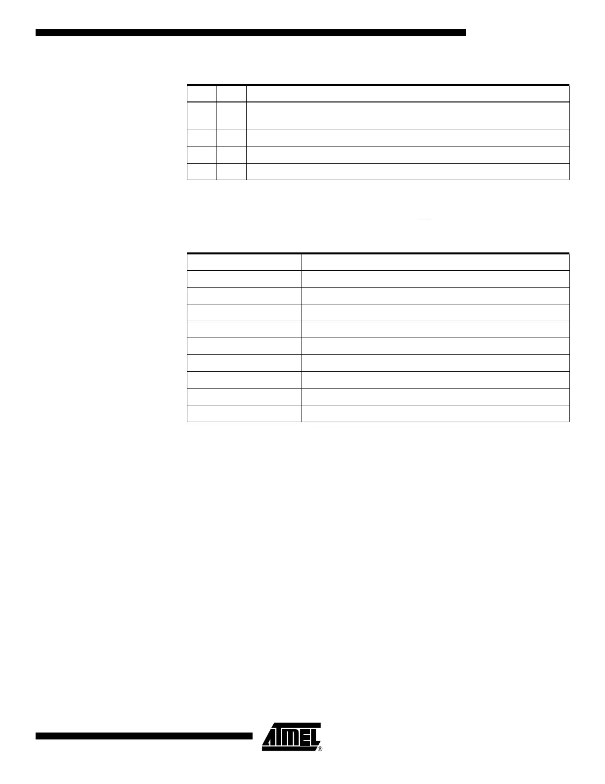
Table 56. XA1 and XA0 Coding
(1)
XA1 XA0 Action when XTAL1 is Pulsed
00
Load Flash or EEPROM Address (High or low address byte determined by
BS1).
0 1 Load Data (High or Low data byte for Flash determined by BS1).
1 0 Load Command
1 1 No Action, Idle
Table 57. Command Byte Bit Coding
Command Byte Command Executed
1000 0000 Chip Erase
0100 0000 Write Fuse Bits
0010 0000 Write Lock Bits
0001 0000 Write Flash
0001 0001 Write EEPROM
0000 1000 Read Signature Bytes and Calibration Byte
0000 0100 Read Fuse and Lock Bits
0000 0010 Read Flash
0000 0011 Read EEPROM