INSTALLATION and POWER
page 1 – 4
D-16 / Feb 2003
CONSOLE
2-TRACK
MULTI-TRACK
AC BREAKER
BOX
DEVICE 1
DEVICE 2
DEVICE N
CONSOLE POWER SUPPLY
CONTROL ROOM POWER AMP
STUDIO POWER AMP
OTHER
POWER COMPANY
EARTH GROUND
HEAVY
(#4 or #6)
COPPER
WIRE
HIGH POWER
EQUIPMENT RACK
COPPER ROD
SOIL
3-wire ground or separate wire run from chassis
EFFECTS RACK
MIC PANEL
GND
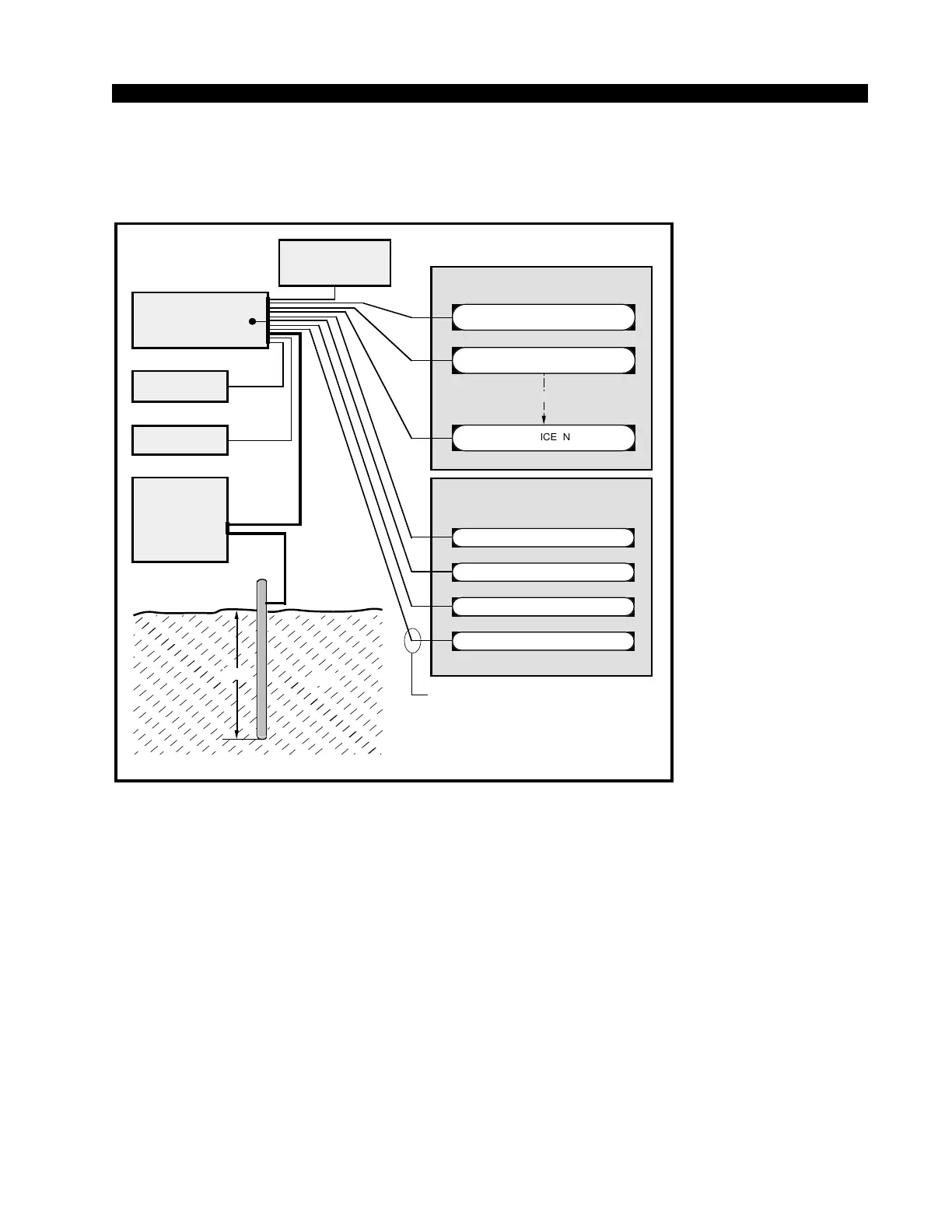
TYPICAL SYSTEM
GROUNDING SCHEME
etc.
3–5 ft.
Tie the console ground lug
terminal strip to the system
earth ground. Tie every piece
of equipment in the entire
audio system to the console
ground lug terminal strip.
earth ground point is inaccessible, tie the console ground lug to the
power company earth conductor at the main breaker box (see drawing
"Typical Grounding Scheme" below).
Each piece of equipment should be connected by its own ground
wire (usually the round third pin on the AC cord). This means that every
AC outlet must have a separate conductor run to the console ground
lug; the outlets cannot be daisy-chained as is normally encountered in
commercial and residential AC systems. Any equipment not supplied
with 3-wire AC cables must have individual ground wires (16 gauge or
larger) connected to their chassis grounds and then run to the console
ground lug terminal strip.
Further Grounding Details
Check all equipment to be absolutely certain that each unit is power
transformer isolated from the AC mains to prevent safety hazards.
It is assumed that in each piece of audio equipment the audio ground
and the chassis are tied together at some point. Any piece of equipment
lacking a grounded chassis is likely to be prone to interference
problems.