page 5 – 6
D-16 / Feb 2003
MONITOR SECTION
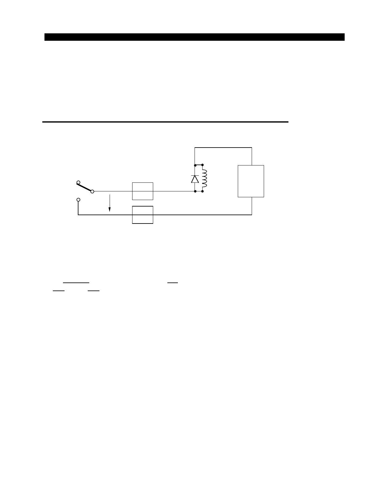
On-Air Tally Circuit
For controlling “on-air” tally function, a relay is provided. The tally is
activated when any channel set for CR mute is turned on or put into cue.
The relay connections are available at the “LINE IN 9-10, TB IN”
DB-25 connector mounted on the rear of the console. Connect the on-air light
to the external user-provided relay. Do not bring on-air light AC connections
to any pin of any connector on the console.
PIN
9
CONNECTOR PIN
ON "LINE IN 9-10,
TB IN" DB-25
YOUR
POWER
SUPPLY
–
TYPICAL CONTROL ROOM ON-AIR TALLY CIRCUIT
USER-SUPPLIED RELAY TRIGGERED BY CONSOLE CR MUTE CIRCUI
PIN
21
+
INTERNAL AIR
TALLY RELAY
COM
+
–
1N4002
ECG
B40240
or equiv.
relay
RELAY CIRCUIT POWERED BY USE
SUPPLIED EXTERNAL SUPPLY
N.O.
N.C.
2A
max
30VDC