page 5 – 7
D-16 / Feb 2003
MONITOR SECTION
Hook-Ups
Monitor Outputs
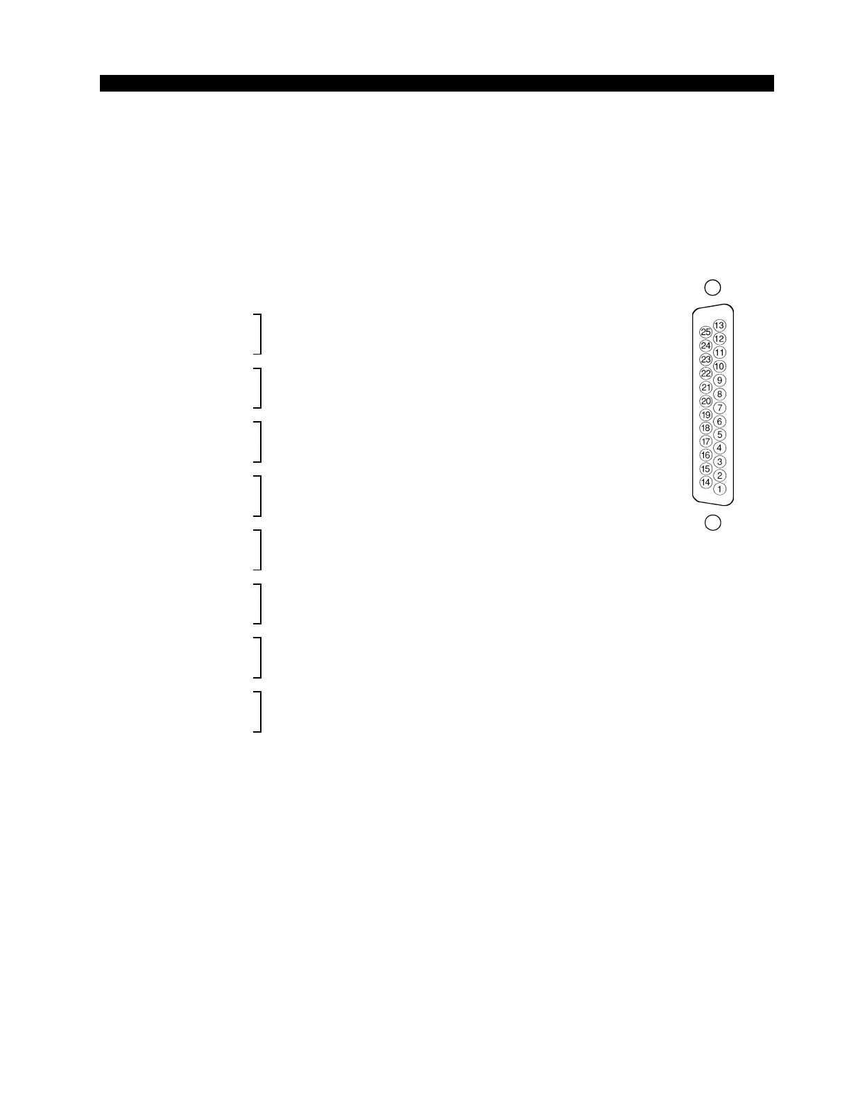
All user wiring takes place at the “MONITORS” DB-25 multi-pin
connectors mounted on the rear of the console. All audio signals are
+4dBu, analog stereo. A pinout drawing on page 5-8 shows all wiring
connections at a glance.
Pin 24 – HI
Pin 12 – LO CR Lt Out
Pin 25 – SH
Pin 10 – HI
Pin 23 – LO CR Rt Out
Pin 11 – SH
Pin 21 – HI
Pin 9 – LO ST Lt Out
Pin 22 - SH
Pin 7 – HI
Pin 20 – LO ST Rt Out
Pin 8 – SH
Pin 18 – HI
Pin 6 – LO ST Pre Lt Out
Pin 19 – SH
Pin 4 – HI
Pin 17 – LO ST Pre Rt Out
Pin 5 – SH
Pin 15 – HI
Pin 3 – LO HDPN Lt Out
Pin 16 – SH
Pin 1 – HI
Pin 14 – LO HDPN Rt Out
Pin 2 – SH
Tallys
User wiring of tallies takes place at the “LINE IN 9-10, TB IN” DB-
25 multi-pin connector mounted on the rear of the console. A pinout
drawing on page 5-9 shows all wiring connections at a glance.
Pin 21 - CR Tally N.O.
Pin 9 - CR Tally COM.
Pin 22 - Analog Ground
Pin 7 - Tally 2 N.O.
Pin 20 - Tally 2 COM.
Pin 8 - Analog Ground
Typical DB-25
connector