page 3 – 6
D-16 / Feb 2003
FADER SECTION
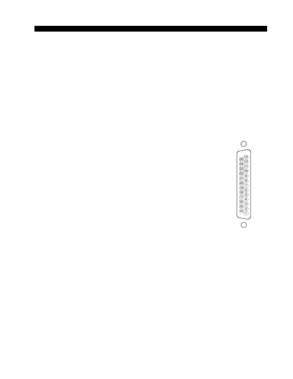
Typical DB-25
connector
Logic Control Ports
The D-16 console has eight LOGIC PORTS located on the rear of the
console and can be used to control local machines, such as cart machines, CD
players, etc., or with talent panels for mic signals. A pinout drawing on page
3-12 shows all wiring connections at a glance.
Pin 1 – ON +
Pin 2 – Digital Ground
Pin 3 – OFF -
Pin 4 - Cough +
Pin 5 - Digital Ground
Pin 6 - TB -
Pin 7 - Ready +
Pin 8 - Digital Ground
Pin 9 - Start -
Pin 10 - Stop +
Pin 11 - Digital Ground
Pin 12 – Tally -
Pin 13 – Audio Ground
Pin 14 - ON -
Pin 15 - OFF +
Pin 16 - Digital Ground
Pin 17 - Cough -
Pin 18 - TB +
Pin 19 - Digital Ground
Pin 20 - Ready -
Pin 21 - Start +
Pin 22 - Digital Ground
Pin 23 - Stop -
Pin 24 - Tally +
Pin 25 - Digital Ground
MIC PORT FUNCTIONS
The mic port logic functions are ON, OFF, COUGH, TALKBACK, and
ON TALLY. These are normally used in connection with a user-provided
talent panel containing switches to be operated by a mic user, often located
in the Studio.
ON LOGIC INPUT - used to connect an external user-supplied button to
activate the microphone’s fader, just as if the fader’s ON BUTTON had been
pressed.
OFF LOGIC INPUT — used to connect an external user-supplied button
to deactivate the microphone’s fader, just as if the fader’s OFF BUTTON had
been pressed.
COUGH LOGIC INPUT — used to connect an external user-supplied
button to activate the microphone fader’s COUGH LOGIC. This acts like a
temporary, or momentary, OFF button, in that, if the microphone is active,