page 3 – 3
D-16 / Feb 2003
FADER SECTION
Hook-Ups
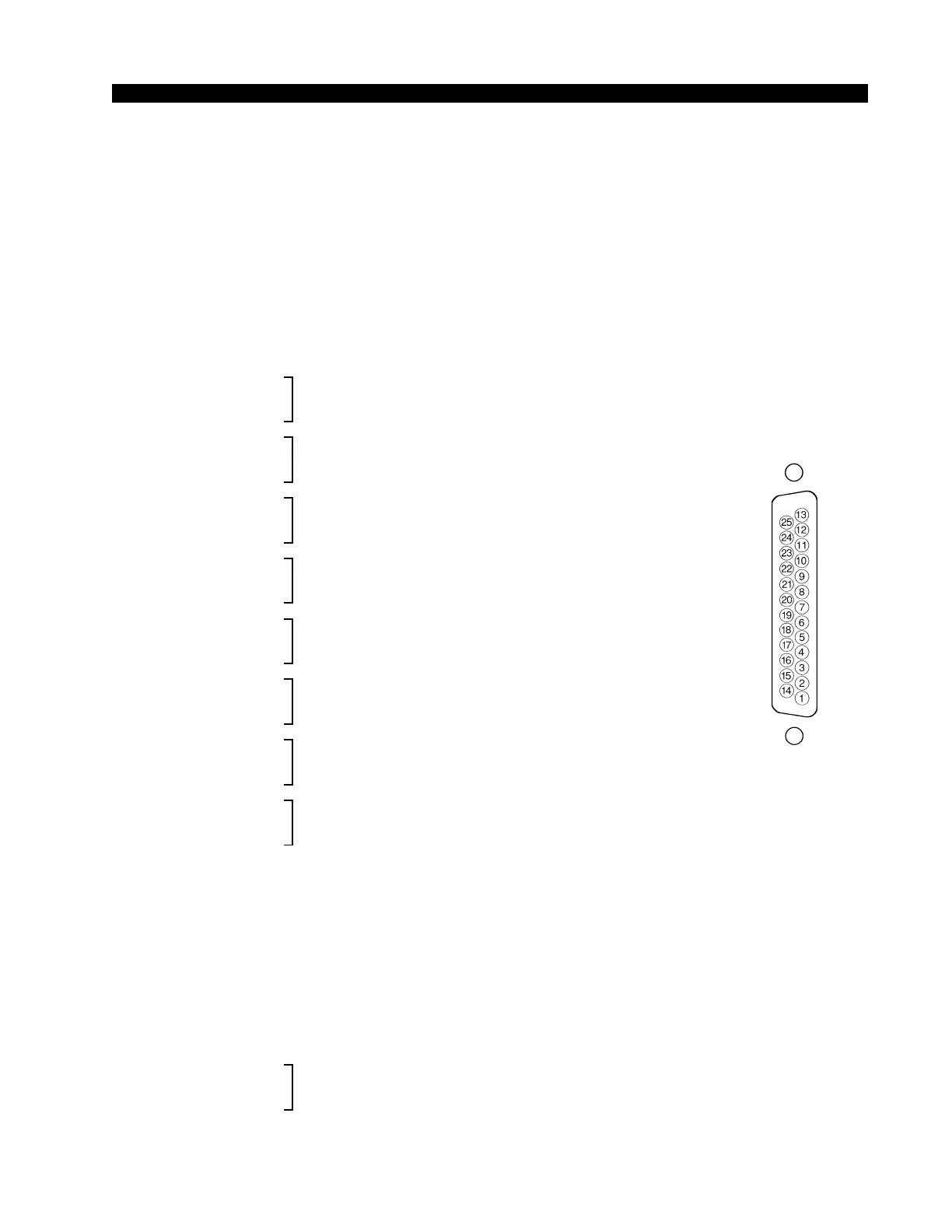
As stated before, all user wiring takes place at DB-25 multi-pin connec-
tors mounted on the rear of the console.
Microphone Inputs
Audio connection for mic inputs/outputs takes place at “MIC IN/OUT”
DB-25 connector. The mic input level is nominally -50dBu. All signals are
analog mono. A pinout drawing on page 3-9 shows all wiring connections at
a glance.
Pin 24 – HI
Pin 12 – LO Mic 1 In
Pin 25 – SH
Pin 10 – HI
Pin 23 – LO Mic 2 In
Pin 11 – SH
Pin 21 – HI
Pin 9 – LO Mic 3 In
Pin 22 - SH
Pin 7 – HI
Pin 20 – LO Mic 4 In
Pin 8 – SH
Pin 18 – HI
Pin 6 – LO Mic 1 Out
Pin 19 – SH
Pin 4 – HI
Pin 17 – LO Mic 2 Out
Pin 5 – SH
Pin 15 – HI
Pin 3 – LO Mic 3 Out
Pin 16 – SH
Pin 1 – HI
Pin 14 – LO Mic 4 Out
Pin 2 – SH
Stereo Line Analog Inputs
Audio connection for analog stereo inputs takes place at three DB-25
connectors: “LINE IN 1-4”, “LINE IN 5-8”, “LINE IN 9-10, TB IN” (this
connector also include TB IN connections). The analog stereo signal level is
+4dBu balanced. A pinout drawing on page 3-10 shows all wiring connec-
tions at a glance.
DB-25 “LINE IN 1-4” Connector
Pin 24 – HI
Pin 12 – LO Line 1 Lt In
Pin 25 – SH
Typical DB-25
connector