page 5 – 5
D-16 / Feb 2003
MONITOR SECTION
the signal level is approaching a clipping (distorted) level. The
next ten LEDs are yellow, indicating a normal level range, and
the remaining LEDs are green. The left member of the pair
indicates the level of the signal’s left channel, while the right
member of the pair indicates the level of the signal’s right
channel. Peak, Over, and Low indications are also provided.
The first VU METER PAIR shows the level of the PGM
output, while the second VU METER PAIR (the SWITCHED
METER PAIR) shows the level of the signal that is selected for
it.
The SWITCHED METER PAIR can meter any signal
appearing at a console input connector, in which case the
input’s left signal appears on the left meter and the input’s right
signal appears on the right meter.
The SWITCHED METER PAIR can meter PGM, AUD, or
the combination of MONO1 and MONO2, with MONO1
appearing on the left meter and MONO2 on the right meter.
If any channel is placed in cue, or if the TALKBACK
button is being held down, the SWITCHED METER PAIR
will automatically switch to meter CUE on the left meter and
the console’s talkback bus on the right meter. The SWITCHED
METER display (see below) switches to show “Q/TB”.
The SWITCHED METER PAIR can meter the caller feed
mix-minus buses (CF1 on the left meter and CF2 on the right
meter), or the general purpose mix-minus buses (MXM1 on
the left meter and MXM2 on the right meter).
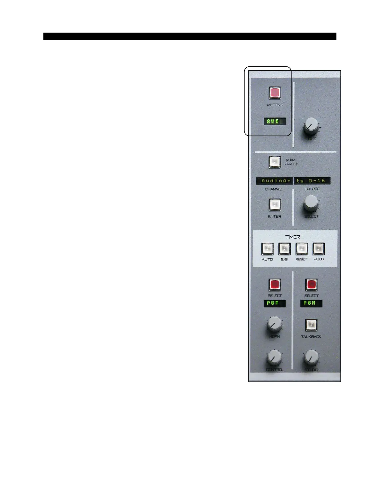
METER SELECT BUTTON. - selects the source for the
switched meter pair.
METER DISPLAY - four character display shows the
source that has been selected for metering by the SWITCHED
METER PAIR.
Tallys
The console has two tally outputs. The first tally output is
used to drive user-provided external circuitry that will in turn
operate the control room on air indicator, and is called the ON
AIR TALLY. It is automatically activated whenever the con-
trol room mute is activated. Thus, turning on any module that
activates the control room mute also turns on the ON AIR
TALLY. The second tally is independent of muting, and can be
used as a studio on air tally, as a skimmer control, or for any
other application requiring a logic signal that depends on the
ON status of one or more inputs.
Ask the technical person in charge of the console if TALLY
2 is used, and if so, what it is set up to do.