32 AutoFarm GPS AutoSteer
Valve Type Installation Procedures
Installation Instructions
1. Refer to Figure 3-18 for a detailed hose diagram and follow the instructions below.
2. Connect a hose from the “Press” port on the AutoFarm steering valve to the pressure port on the tractor power beyond sys-
tem. Use a quick coupler or hose adapter that matches the power beyond port on the tractor. This hose will provide oil pres-
sure to the AutoFarm valve on demand.
3. Connect a hose from the Tank port on the Autofarm steering valve to the tank port on the tractor power beyond system. Use
a quick coupler or hose adapter that matches the power beyond port on the tractor. This hose will connect the AutoFarm
valve to tank.
4. Connect a hose from the LS OUT port on the Autofarm steering valve to the LS port on the tractor power beyond system.
Use a quick coupler or hose adapter that matches the power beyond port on the tractor. This hose will connect the Auto
-
Farm load sense to the tractor hydraulic system to stroke up the pump.
5. Disconnect the LS hose from the Orbitrol and install a Tee adapter. Reconnect the vehicle’s LS hose to the tee adapter.
6. Connect a hose between the “LS Orbitrol” port on the AutoFarm steering valve and the tee adapter that was previously
installed on the LS port on the Orbitrol. This hose will provide a pressure signal to the AutoFarm pressure transducer to
allow AutoSteer kick-out when the driver turns the steering wheel.
7. Connect a hose between the “Right” port on the Autofarm steering valve and the right steering hose on the Orbitrol. You
may install the tee adapter anywhere along the right steering line in a convenient location.
8. Connect a hose between the “Left” port on the steering valve and the left steering hose on the Orbitrol. You may install the
tee adapter anywhere along the left steering line in a convenient location.
9. Individually check each hose connection at both ends and confirm that it matches the hose diagram in Figure 3-18. Wrong
hose connections can cause immediate pump damage when the engine is started.
10. Confirm that the AutoFarm steering valve is configured internally for a Closed Center power beyond installation with the
correct orifices and/or plugs installed.
11. Adjust the relief valve.
12. Proceed to system calibration and tuning.
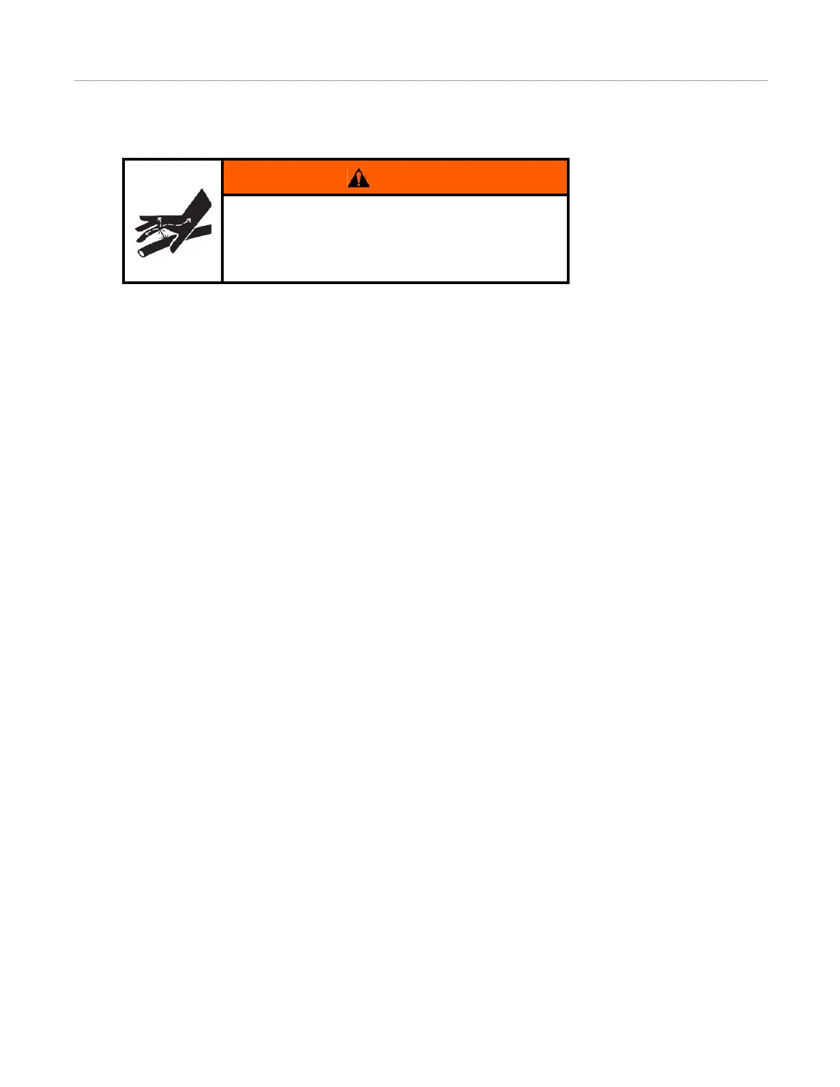
WARNING
High-Pressure Fluid Hazard
Read the Owner’s Manual before installation. Wear hand
and eye protection while performing hydraulic system
maintenance. Relieve hydraulic system pressure before
servicing the hydraulic system.